7.0 Maintenance
_________________________________________________________________________________________
CC1132751D 17
7.0 Maintenance
WARNING !
SERVICING MUST ONLY BE CARRIED-OUT BY
TRAINED SERVICE ENGINEERS COMPETENT IN THE
MAINTENANCE, MAINS ELECTRICAL SUPPLY AND
STARTER EQUIPMENT
7.1 Routine Service
The work listed must be carried-out at the indicated running
hours, which must be regarded as a maximum. In dusty, hot or
humid conditions, more frequent servicing may be necessary.
On RS units after long periods, speed control unit capacitors and
cooling fan(s) should be replaced to ensure reliability of the unit.
7.2 Service Kits
If you are unable to carry-out the work safely in the required
manner, your Hydrovane Distributor will be pleased to help.
Use genuine parts and approved oils during routine servicing,
the following service kits are available:
Oil change kit, 2000 hour/12 months, use KOHR457.
Maintenance kit, 4000 hour/2 year, use KMHR457 or
KMHR457LS. Serial numbers: HR04-000210-1605, HR05-
000445-1605 & HR07-000790-1601.
Full overhaul/top-up kit, 20000 hour/10 year, use KTHR4,
KTHR5, KTHR7 (inc. KWHR457) use with KMHR kit.
Additional kits available for full product support are as follows:
Solenoid valve kit, 8000 hour/4 year, use KSVDOLHR457,
KSVSDHR457.
Contactor kit, non-scheduled item, use KCHR457DOL,
KCHR457RS, KCHR457SD
Electrical kit, 20000 hour/10 year, use KEHR457DOL,
KEHR457RS, KEHR457SD
Oil Seal and Wear sleeve kit, 20000 hour/10 year, use
KWHR457 (Inc in KT KIT).
Motor bearing kit (HEBEI Motor), 20000 hour/10 year, use
KBH132 (HR04), KBV132 (HR05/07)
7.3 Service Instructions
WARNING !
STOP THE COMPRESSOR AND ISOLATE FROM THE
MAINS ELECTRICAL SUPPLY. LOCK THE ISOLATOR
IN THE OFF POSITION. FIT A SAFETY NOTICE
ADVISING THAT WORK IS BEING CARRIED OUT ON
THE COMPRESSOR.
CLOSE THE AIR OUTLET VALVE TO ISOLATE THE
COMPRESSOR FROM THE AIRLINE SYSTEM. FIT A
SAFETY NOTICE ADVISING THAT IT IS NOT TO BE
OPENED.
DO NOT PROCEED UNTIL THE AIR PRESSURE
GAUGE READS ZERO !
AVOID UNNECESSARY CONTACT WITH HOT OIL
AND
COMPONENTS.
GLOVES
ARE
RECOMMENDED IF DRAINING OIL WHEN THE
COMPRESSOR IS HOT!
7.4 Panel Removal
Unlock and open the hinged front door panel to allow removal of
the top panel. Remove any fixing screws and pull the top panel
from the location slots and lift clear of the compressor.
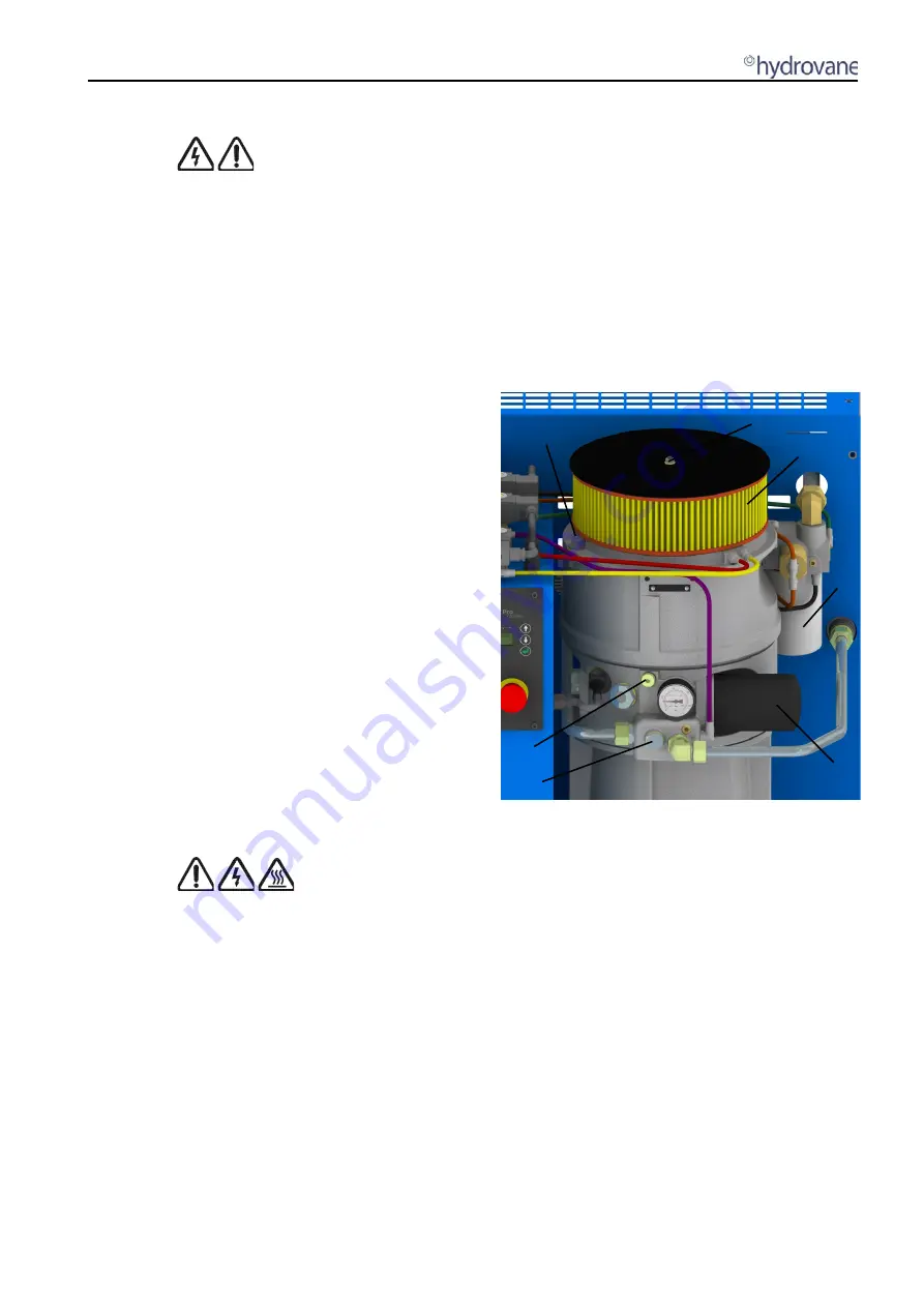
7.5 Oil Filling/Draining (Fig.7.1)
Remove filler plug (A) with bonded seal (B), remove and retain
the level plug (C).
Place a suitable container below the oil drain point, remove drain
plug (D) with bonded seal (E) and allow oil to drain.
When draining is complete, replace the drain plug and clean
away any oil spillages.
Fill with approved oil to overflow from the level plug. Stop filling,
replace the level and filler plugs, and clean away any spillage.
If the oil filter has been replaced, run the compressor for a short
time (30 seconds) and re-check the oil level.
Fig 7.1 Filler Plug, Air Filter, Separator, Oil Drain
and Filter
7.6 Oil Filter (Fig 7.1)
Unscrew oil filter (F) anti-clockwise, minimise spillage from the
canister and discard in a safe manner.
Using a new filter, smear a small amount of oil onto the seal,
screw in clockwise, hand tight only.
7.7 Air Filter (Fig.7.1)
Remove M6 Nut (G) with bonded seal (H), remove the cover
plate. Lift off the air filter element (J) and discard in a safe
manner.
Using a new air filter element, replace over filter support and fix
the cover plate back on with, nut and bonded seal.
7.8 Oil Separator (Fig.7.1)
Unscrew oil separator (K) anti-clockwise and discard in a safe
manner.
Using a new separator, smear a small amount of oil onto the
seal, screw clockwise, hand tight only.
A B
C
D E
F
K
G H
J
Содержание HR04
Страница 1: ...HR04 HR07 Models User Handbook Original Instructions CC1132751D 10 2018 GB...
Страница 2: ......
Страница 23: ......


