


Hydro-View User Guide HD0531 Rev 2.0.0 43
Event Log –
Compatible sensors will store any event log in to its internal memory. The event
log can be downloaded to a file to enable diagnostics on the sensor to take place. Please
contact [email protected] for help using the saved data file.
6.1.3
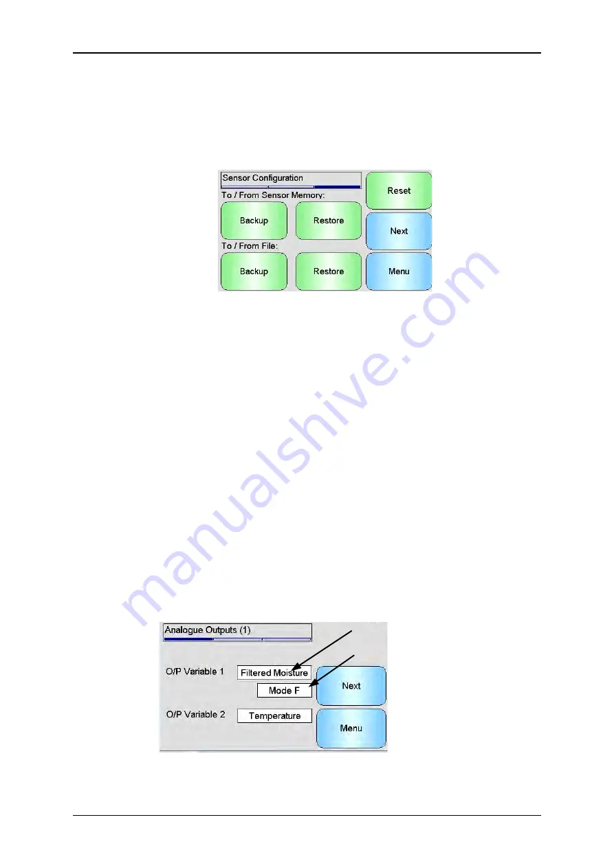
Sensor Configuration
This screen is used to back up or restore all sensor settings.
Figure 25: Sensor Backup / Restore Screen
Backup to File
- Backup all of the sensors settings to a USB memory stick. Enter a file
name when prompted. This file is stored on the USB stick in a folder
\HydroView_IV\BackUpFiles\ in a format compatible with Hydro-Com, the Hydronix PC
based sensor configuration and calibration software.
Restore from File
- The sensors settings may be restored from a Hydro-Com compatible
backup file. This file must be on a USB memory stick in the folder
\HydroView_IV\BackUpFiles\. The file should then be selected from a list of possible files.
Restoring a sensor will overwrite all of its settings.
Backup to sensor memory-
All Hydronix sensors utilising firmware HS0102 and above
have the ability to store the sensor configuration settings to its internal memory. This
facility enables the user to back up the sensor configuration so it can be restored at a later
date if required
Restore From sensor Memory-
Restore the sensor using the sensors internal memory
Reset-
During manufacture all settings are stored in a reserved memory location to enable
the sensor to be restored to default. This facility is only available on selected sensors.
6.2
I/O
6.2.1
Analogue Outputs (1)
Output Variable
Output Measurement Mode
(If applicable)
Figure 26: Analogue Output Screen 1
The analogue output is normally configured to be proportional to the percentage moisture
reading. However it is possible to make the analogue output represent other types of
output variables which are selectable from the O/P Variable 1 and O/P Variable 2 options.
Содержание HV04
Страница 4: ...4 Hydro View User Guide HD0531 Rev 2 0 0 ...
Страница 6: ...6 Hydro View User Guide HD0531 Rev 2 0 0 ...
Страница 12: ...12 Hydro View User Guide HD0531 Rev 2 0 0 ...
Страница 14: ...14 Hydro View User Guide HD0531 Rev 2 0 0 ...
Страница 22: ...Mechanical Installation Chapter 2 22 Hydro View User Guide HD0531 Rev 2 0 0 ...
Страница 28: ...Electrical Installation Chapter 3 28 Hydro View User Guide HD0531 Rev 2 0 0 ...
Страница 78: ...Material Calibration Chapter 6 78 Hydro View User Guide HD0531 Rev 2 0 0 ...
Страница 80: ...Default PIN Codes Appendix A 80 Hydro View User Guide HD0531 Rev 2 0 0 ...
Страница 82: ...USB Memory Stick file format Appendix B 82 Hydro View User Guide HD0531 Rev 2 0 0 ...
Страница 84: ...Quick Start Rules Appendix C 84 Hydro View User Guide HD0531 Rev 2 0 0 ...
Страница 86: ...Frequently Asked Questions Appendix D 86 Hydro View User Guide HD0531 Rev 2 0 0 ...
Страница 92: ...Document Cross Reference Appendix G 92 Hydro View User Guide HD0531 Rev 2 0 0 ...


