


3.4
BLADE BRUSH ADJUSTMENT
The blade brush is properly set when the machine leaves the factory but it will wear during operation and needs to be
adjusted periodically. The blade brush assembly is found behind the drive side door and is shown below. As shown, there
are two springs on socket head screws holding the brush assembly against the blade. There is also an adjusting socket set
screw with a hex nut on it. To adjust the assembly, loosen the hex nut with a 9/16” wrench and turn the set screw counter
clockwise with a 3/16” Allen key. This will move the brush closer to the blade. Adjust the set screw so that the brush cleans
to the bottom of the blade gullets and tighten the hex nut. The brush should be replaced as it becomes worn to
approximately 70% of its original 4” diameter. When a new brush is installed brush adjustment is required
(Replacements can be purchased through your Hyd·Mech Group dealer)
BLADE TRACKING
First, inspect the blade wheels for wear or damage and repair as required. Blade tracking adjustment should always begin
at the wheel where the tracking is farthest out of specification. Using the instructions below, adjust the worst wheel, jog the
blade and recheck both wheels. Repeat this process until both wheels are within specification
M16 = 0.250 to 0.270” (6.35 mm to 6.56 mm) of tooth over hang from the front of the wheel.
M20 = 0.260 to 0.300” (6.6 mm to 7.62 mm) of tooth over hang from the front of the wheel.
Both the drive and idler wheels are factory set a certain distance from the wall behind the wheel. Adjustment should not
be required unless the wheel is being replaced. On the drive wheel there is a large hex head bolt and four set screws in
a “push/pull” arrangement. For the idler wheel there is single adjuster assembly in the center of the idler shaft under the
cover on the front of the head. Hyd
·
Mech Service should be contacted before making any adjustment to the wheel
position.
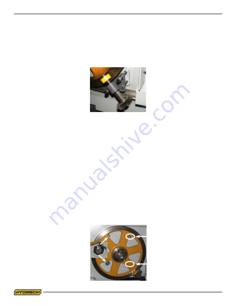
DRIVE WHEEL ADJUSTMENT
The drive wheel has two mounting bolts and two adjusting bolt assemblies. The mounting bolts (A) should be loosened
but remain snug before making any adjustment to the bolt assemblies (B & C). Both of the bolt assemblies should be ad-
justed by equal amounts. To adjust the bolt assemblies, release blade tension slightly, loosen bolts “B” and turn bolts “C”
in or out by equal amounts and tighten bolts “B”. Turning bolts “C” in will pull the blade onto the wheel and turning them
out will push the blade off the wheel. Check the tracking movement after each one quarter turns of bolts “C” by running the
blade at minimum speed. When the tracking is within specification, tighten bolts “A”.
A
A
B
C
Содержание M16A
Страница 2: ...2 ...
Страница 3: ...2 ...
Страница 38: ...2 20 ...
Страница 55: ...4 1 ELECTRICAL SCHEMATICS SEE PDF ON ATTACHED CD SECTION 4 ELECTRICAL ...
Страница 56: ...4 2 ...
Страница 60: ...6 1 MECHANICAL ASSEMBLY DRAWINGS PARTS LIST SEE PDF ON ATTACHED CD SECTION 6 MECHANICAL ASSEMBLIES ...
Страница 61: ...6 2 ...
Страница 68: ...7 7 AUTOMATIC MODE SCREEN Fig 8 ...
Страница 72: ...8 2 M16A LAYOUT ...
Страница 74: ...8 4 M20A LAYOUT ...
Страница 76: ...9 2 ...


