background image


Error messages / Troubleshooting


FluidAqua Mobil - FAM10/15-P 

en(us) 

Page 90 / 124

BEWA FAM10-15-P 4052078 en-us 2015-11-05.doc 

2015-11-05


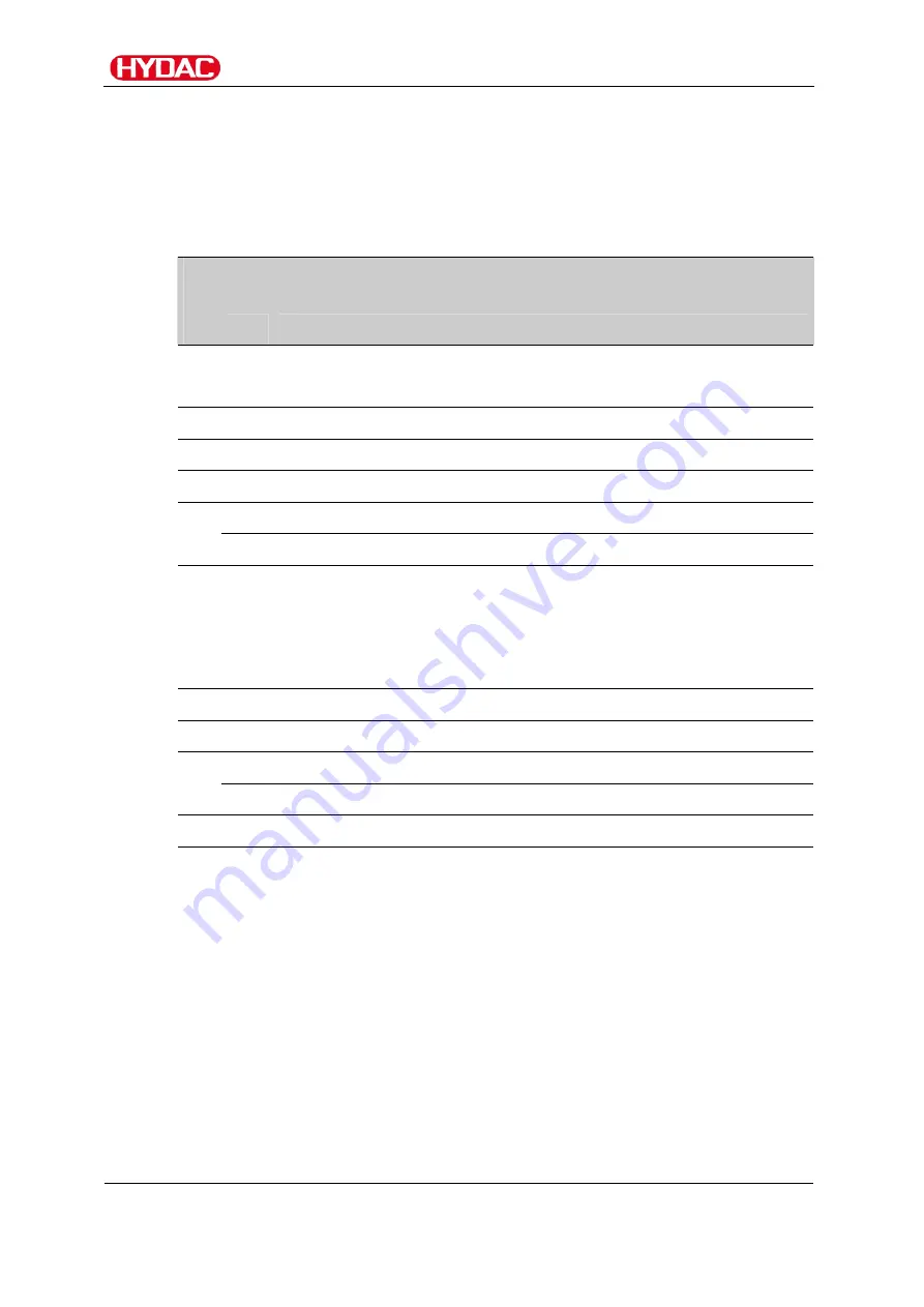
3. FAM outlet is blocked


Cause: 

The level must reach the MIN switch point within 5 
minutes once the MAX switch point in the vacuum 
column has been reached. 

Remedy: Perform 

the 

following 

steps: 

Step 


Description 

1.  

Message: 


3. FAM outlet is blocked 

2. 


Check all of the locking devices in the return line for flow. 

3. 


Actuate ESC key and reset failure with the F3 key. 

4. 


Start the unit by pressing the F1 key. 

->a.  The fault is repeated. 

-> proceed to Step 6. 

5. 

->b.  The fault is not repeated. 

-> proceed to Step 11. 

6. 


Check the evacuation pump for proper functioning. 
Check the return valve. 
Check the suction line for constrictions. 
Check the filter for flow. 

7. 


Actuate ESC key and reset failure with the F3 key. 

8. 


Start the unit by pressing the F1 key. 

->a.  The fault is repeated. 

-> proceed to Step 10. 

9. 

->b.  The fault is not repeated. 

-> proceed to Step 11. 

10.   

Contact the HYDAC service department. 

11.   

The fault is repaired. 


Содержание FluidAqua Mobil FAM 10-P

Страница 1: ...FAM 10 P FAM 10 15 P FluidAqua Mobil Operating and Maintenance Instructions English translation of original operating instructions Document No 4052078 ...

Страница 2: ...on Representative Mr Günter Harge c o HYDAC International GmbH Industriegebiet 66280 Sulzbach Saar Telephone 49 0 6897 509 1511 Fax 49 0 6897 509 1394 E Mail guenter harge hydac com HYDAC FILTER SYSTEMS GMBH All rights reserved No part of this work may be reproduced in any form print photocopy or by other means or processed duplicated or distributed using electronic systems without the written con...

Страница 3: ... instructions 10 Structure of the safety information and instructions 11 Observe regulatory information 11 Proper Designated Use 12 Improper Use or Use Deviating from Intended Use 13 Qualifications of personnel target group 14 Wear suitable clothing 15 Stoppage in an emergency EMERGENCY STOP 15 Unpacking the FAM 15 Transporting the FAM 16 Fork lift 16 Crane 17 Rail Truck 17 Decoding the model code...

Страница 4: ...eck the fill level on the condensate separator 38 Electrical connection of the FAM 39 Check direction of rotation 40 Operating Elements on the FAM 41 Starting up the FAM 42 Switching on the FAM 43 Setting the pressure in the vacuum column 44 Shutting off the FAM 46 Control panel basic SIMATIC PANEL 47 Overview of operating modes and abbreviations 48 Overview of menu structure 49 Changing entering ...

Страница 5: ... filter element on the condensate separator 76 Checking the fill level on the condensate separator 76 Filling the condensate separator 76 Cleaning the suction strainer 77 Rotary vane vacuum pump components 78 Performing an oil change 79 Replacing the Air De oiling Element 80 Replacing the filter element on the fluid filter 81 Testing the Float Switch in the Oil Pan 86 Checking the settings on the ...

Страница 6: ... F2 has tripped 104 28 Heater fuse has tripped 105 29 Check phase sequence 107 30 Malfunction CS flow too low 109 31 Fault CS device error 109 32 Dry running Evacuation Pump 110 33 Vacuum column overflow drain vacuum column and troubleshoot cause 111 34 Oil pan too full drain oil pan and seal leak 113 37 Saturation oil 90 Measurement with CS 1xxx not possible 114 Spare parts 115 FAM 115 Fluid filt...

Страница 7: ... liability shall be limited to foreseeable damage Claims due to Product Liability shall remain unaffected Technical Support If you have any questions suggestions or encounter any problems of a technical nature please don t hesitate to contact us When contacting us please always include the model type designation and article no of the product Fax 49 0 6897 509 9046 E Mail filtersystems hydac com Mo...

Страница 8: ...o know I determine which topic I am looking for WHERE can I find the information I m looking for The document has a table of contents at the beginning I select the chapter I m looking for and the corresponding page number de HYDAC Filtertechnik GmbH BeWa 123456a de Seite x Produkt Kapitel 200x xx xx The documentation number with its index enables you to order another copy of the operating and main...

Страница 9: ...ll the safety devices are present Secure the hazardous areas which may arise between the unit and other equipment Maintain the unit inspection intervals prescribed by law Document the results in an inspection certificate and keep it until the next inspection Hazard symbols These symbols are listed for all safety information and instructions in these operating instructions which indicate particular...

Страница 10: ...ty information and instructions DANGER DANGER indicates a danger with a high risk and which will lead to death or serious injury if not avoided WARNING WARNING indicates a danger with a medium risk and which can lead to death or serious injury if not avoided CAUTION CAUTION indicates a danger with a low risk and which can lead to minor injury if not avoided NOTICE NOTICE indicates a danger which w...

Страница 11: ... signal word indicate the severity of the danger Warning instructions listed before an activity are laid out as follows SIGNAL WORD Type and source of danger Consequence of the danger HAZARD SYMBOL Measures to avert danger Observe regulatory information Observe the following regulatory information and guidelines Legal and local regulations for accident prevention Legal and local regulations for en...

Страница 12: ... water found in solution Proper or designated use of the product extends to the following observing all instructions contained in these operating instructions performing inspection and maintenance work NOTICE Impermissible operating conditions The unit will be damaged Only use the powerpack in conjunction with Aviation phosphoric ester e g Skydol or Hyjet Do not use the FAM together with water or ...

Страница 13: ... connection with the media mentioned below Any use extending beyond or deviating therefrom shall not be considered intended use HYDAC Filter Systems GmbH will assume no liability for any damage resulting from such use The risk is borne exclusively by the machine owner Improper use may result in hazards and or will damage the unit Examples of improper use Operation in potentially explosive atmosphe...

Страница 14: ... and several years work experience They are able to assess and perform the work assigned to them they are also able to recognize potential hazards Activity Person Knowledge Transport storage Forwarding agent Specialist personnel Proof of knowledge of cargo securing instructions Safe handling operation of hoisting and lifting equipment Hydraulic electrical installation first commissioning maintenan...

Страница 15: ...ear work safety shoes Stoppage in an emergency EMERGENCY STOP In the event of an emergency turn the main switch by 90 in a counter clockwise direction to shut down the entire unit The entire unit downstream of this switch is voltage free and depressurized Normal pressure is restored in the vacuum column after approx 1 minute Unpacking the FAM Before delivery the FAM is inspected for leaks and prop...

Страница 16: ...damaged Never use the components to push or pull the unit Use only the grips provided for shifting Drain the unit completely before transport Seal off the inlets and or outlets Shift the FAM manually using the rollers When doing so use only the grips provided on the FAM frame for pushing Before shifting the unit make sure to release the hand brake on the steering rollers Once the FAM is in its new...

Страница 17: ... unit will be damaged Components will be damaged destroyed Use only suitable lifting accessories to raise or lash the unit Take care to ensure that the lifting accessories do not cause any pressures to be brought to bear against the components on the unit Rail Truck For transport by rail or truck supports must be placed under the mobile unit so that the rollers are subjected to no load pressure Th...

Страница 18: ...idAqua Mobil FAM10 15 P en us Page 18 124 BEWA FAM10 15 P 4052078 en us 2015 11 05 doc 2015 11 05 Decoding the model code label Details for identifying the filtration unit can be found on the name plates on the unit and the components ...

Страница 19: ... following information can be found on the name plate of the unit Row Description Part No Part number S N Serial number year of production Power Power consumption Voltage Grid Voltage power supply Frequency Frequency Current Current consumption Protection Class Protection class electrical Pressure max Operating pressure maximum Pressure IN Maximum permissible pressure at IN port Pressure OUT Maxim...

Страница 20: ...rfect order Any damage in transit is to be reported to the forwarding agent or the department in charge immediately the unit may not be commissioned until this damage is properly remedied The following items are supplied Qty Designation 1 FluidAqua Mobil 1 Technical Documentation const of Operating and maintenance instructions Electrical wiring diagram Test protocol Manufacturer s declaration Decl...

Страница 21: ...ified water and a large percentage of the water to be found in solution The integrated fluid filter ensures an efficient separation of solid particles The drying and degassing of the medium is achieved by the neg pressure in the vacuum column FAM Versions Stationary FAM xx 1 Mobile FAM xx 2 In comparison to the stationary version the mobile version of the FAM has 2 casters 2 bock rolls Suction hos...

Страница 22: ...M5 1 000 7 000 FAM 10 15 7 000 15 000 FAM25 15 000 25 000 FAM45 25 000 35 000 FAM60 35 000 45 000 FAM75 45 000 FAM95 Generally speaking however it must be taken into account that the design depends on the application the fluid and the ambient temperature the fluid amount and the water input into the system These exercise a great influence over the dewatering performance It is for that reason that ...

Страница 23: ...FAM Description FluidAqua Mobil FAM10 15 P en us Page 23 124 BEWA FAM10 15 P 4052078 en us 2015 11 05 doc 2015 11 05 FAM system components ...

Страница 24: ... vacuum setting 15 Pressure sensor for vacuum measurement 16 Vacuum pump 19 Vacuum column level sensor 24 Float switch oil pan 25 Vacuum column drainage 26 3 2 directional control valve 27 Temperature sensor optional for heater 28 Vacuum pump drainage 29 Level sensor for vacuum pump 30 Ball valve at the inlet IN 33 Active carbon filter 34 Condensate separator 35 Venting valve 36 Silencer 37 Conden...

Страница 25: ...FluidAqua Mobil FAM10 15 P en us Page 25 124 BEWA FAM10 15 P 4052078 en us 2015 11 05 doc 2015 11 05 Dimensions The different versions of the FAM series have the following illustrated dimensions Stationary version ...

Страница 26: ...Dimensions FluidAqua Mobil FAM10 15 P en us Page 26 124 BEWA FAM10 15 P 4052078 en us 2015 11 05 doc 2015 11 05 Mobile version ...

Страница 27: ...Hydraulic diagram FluidAqua Mobil FAM10 15 P en us Page 27 124 BEWA FAM10 15 P 4052078 en us 2015 11 05 doc 2015 11 05 Hydraulic diagram ...

Страница 28: ... and dryer 14 Needle valve for vacuum setting 15 Pressure sensor for vacuum measurement 16 Vacuum pump 19 Vacuum column level sensor 20 Pump to the ContaminationSensor CS1000 optional 21 ContaminationSensor CS1000 Optional 22 Pressure relief valve CS1000 optional 23 Pressure relief valve CS1000 optional 24 Float switch oil pan 25 Vacuum column drainage 26 3 2 directional control valve 27 Temperatu...

Страница 29: ...ative pressure setting 14 continuously measured at the negative pressure sensor 15 and displayed on the SIMATIC operating panel in the control cabinet The fluid percolates downwards in the vacuum column over a special tower packing and collects in the lower area After reaching the Max level 02 the evacuation pump 7 switches on and now permanently conveys the fluid out through the fine filter 9 to ...

Страница 30: ...ol of the Siemens S7 series monitors the functioning of the unit Malfunction and error messages are displayed in plain text in the correspondingly available national language All E STOP messages will lead to a direct switch off of the unit After the FAM is shut down using the control panel the filling pump and the rotary vane vacuum pump together with its switching conveyor pump when a CS is prese...

Страница 31: ...und there in continuous operation Purifying and transferring by pumping The FAM is connected to the contaminated oil tank with the suction hose and pumps the fluid into the tank for the purified oil while cleaning it at the same time A Waste oil tank B Pure oil tank The fill level of clean oil tank is to be monitored constantly during this process to prevent overfilling You achieve permanently bet...

Страница 32: ...ent gas is inhaled over an extended period of time Setting up the FAM Observe the following points when setting up the unit Set up the unit horizontally on a level surface Special mounting is not required Lock the immobilization brakes on the wheels to avoid unintended movement of the unit Set up the unit directly beside the tank that is to be cleaned Observe the maximum permitted suction pressure...

Страница 33: ...external thread 2 Adapter Adapter G1 A external thread 3 FAM outlet connector 18L M26x1 5 external thread 4 Adapter Adapter G1 2 A external thread 5 Suction hose connection 28L M36x2 internal thread 6 Adapter Adapter G1 A external thread 7 Pressure hose connection 18L M26x1 5 internal thread 8 Adapter Adapter G1 2 A external thread Output drive type D to ISO 8434 1 Series L corresponds to ISO 1215...

Страница 34: ...nnectors to the unit without initial stress The pressure at the inlet outlet depends on the height differential between the FAM fluid surface in the tank port aspiration height P height and the line losses P line If the FAM is above the fluid surface in the tank determine the pressure as follows P 1 bar P height P line If the FAM is below the fluid surface in the tank determine the pressure as fol...

Страница 35: ...ensity D is Mineral hydraulic oil HLP 0 85 0 90 kg dm Phosphate ester HFDR 1 00 1 10 kg dm Insulating oil 0 90 1 00 kg dm Lubricating oil 0 90 0 95 kg dm Additional threaded connections and pipe bends increase the pressure differential and must be taken into account Keep the height difference between the pump and the oil level in the tank as low as possible Avoid constrictions in the connected hos...

Страница 36: ...he level of the oil NOTICE Contamination too high The unit will be damaged Do not prime directly at the bottom of the tank Do not prime in the sump Never prime without a built in suction strainer The greatest contamination is found on the bottom of the tank All impurities and other particles are deposited on the bottom of the tank Connect outlet OUT Take care to ensure that the maximum pressure of...

Страница 37: ... Check the oil level before star up topping up with vacuum pump oil VE101 if necessary The maximum filling amount for vacuum pump oil VE101 is 0 3 liters The water level is monitored automatically by the integrated float switch while the FAM is in operation A message will appear on the control panel when the MIN MAX filling level has been reached Synthetic vacuum pump oil in accordance with DIN 51...

Страница 38: ...4 Check the oil level through the inspection glass 5 Fill up the vacuum pump oil no higher than the MAX marking We recommend filling up to a level between the MIN and MAX markings The suction strainer is re mounted in reverse order 1 2 3 4 5 Check the fill level on the condensate separator Check the condensate separator level before start up During downtime i e when the FAM is not in operation the...

Страница 39: ...e electrical system may only be done by a properly trained certified electrician The electrical connection of units without connection plugs to the power supply module may only be performed by a technician with corresponding knowledge and skills Make sure that the voltage and frequency specifications on the FAM type label correspond to the existing mains voltage If a plug is present on the FAM or ...

Страница 40: ...jog mode check the direction of rotation of the motors A rotation direction arrow on the fan cover of the motor identifies the correct direction of rotation Make sure there is a clockwise rotating field If this is not the case then the phases can be rotated in the 16A 32 A connection plug with the aid of the phase changing switch in the plug For the 63A version the two phases must be switched on t...

Страница 41: ...Elements on the FAM The following operating elements are to be found on the FAM Item Description A Main switch with E STOP function B Alarm signal lamp yellow C Control panel for details see page 47 D Vacuum gauge to set the pressure in the vacuum column E SensorMonitoring Unit SMU1200 for details see the corresponding operating instructions ...

Страница 42: ...e 42 124 BEWA FAM10 15 P 4052078 en us 2015 11 05 doc 2015 11 05 Starting up the FAM NOTICE Connection IN OUT closed The FAM will be damaged Check to be sure that all of the locking fixtures at the inlet outlet are in open position each time before start up ...

Страница 43: ...but it would contribute decisively to the enhancement of dewatering performance Select the operating mode OM as described on page 57 F1 F2 F3 F4 F1 start FAM F4 switch to MENU1 Press the START key The FAM begins with the starting phase The power unit control switches to the RF D menu The vacuum pump starts up the filling pump conveys and the vacuum column is filled Set the required negative pressu...

Страница 44: ...vacuum column Use the needle valve D to set the pressure in the vacuum column Note that the pressure to be set in the vacuum column is dependent on the operating viscosity and the water content Medium Operating viscosity Pressure setting absolute pressure Hydraulic oil 50 mm2 s 350 mbar Ester oil 50 mm2 s 400 mbar Lubricating oil 300 mm2 s 500 mbar START MENU1 RH P Rel moisture Nominal 30 Actual 3...

Страница 45: ...ve moisture for water contents 100 With free water this means starting with higher pressure such as 500 mbar and reducing the pressure to 250 mbar for example only after the level has fallen below the saturation point 100 Some oils foam intensively when they enter the vacuum chamber This effect is particularly pronounced with high water contents This effect is also to be observed with older oils o...

Страница 46: ... shut off Afterwards all of the pumps will be switched off except for the evacuation pump The evacuation pump runs until the Min fill level in the vacuum column is reached The run down phase status is shown in the display The run down phase status is shown in the display The FAM is once again ready for operation when the Start screen appears on the display F1 F2 F3 F4 Close all locking features in...

Страница 47: ...LP ENTER ACK ESC All functions are input and controlled using this control panel Due to the size of the display it is necessary to radically shorten the texts relating to the operating modes and the functions For an overview of the corresponding abbreviations refer to the following pages NOTICE Pressing several keys together at once Unintended actions Do not press more than two buttons simultaneou...

Страница 48: ...ion only Operating modes Only possible operating modes are displayed DW FT Dewatering and Filtration DWT FT Dewatering up to and Filtration DWT FTB Dewater to Filter to EW H FT Dewater Heat Filter DWT H FT Dewater to Heat Filter DWT H FTB Dewater to Heat Filter to FT Filtration FT H Filter Heat EW FTB Dewater Filter to EW H FTB Dewater Heat Filter to FTT Filter to FTT H Filter to Heat Manual menu ...

Страница 49: ...1 05 doc 2015 11 05 Overview of menu structure Menu1 RH P T Cont ISO SAE NAS OM Operating Mode DW FT DWT FT DWT FTB EW H FT DWT H FT DWT H FTB FT FT H EW FTB EW H FTB FTT FTT H DW FT MAN OPERATOR MANU 1 Manual Operation FP DP MANU 2 VP RV WDV MANU 3 H CSP WFV MANU 4 RP Service SET Language Units Temperature Pressure ...

Страница 50: ...Control panel basic SIMATIC PANEL FluidAqua Mobil FAM10 15 P en us Page 50 124 BEWA FAM10 15 P 4052078 en us 2015 11 05 doc 2015 11 05 Menu2 Intervals an operating hours counter and Configuration ...

Страница 51: ...ombination SHIFT TAB which is marked by framing made up of a line of dashes The changeover to the selected menu is achieved with the key Values can be modified during automatic operation To modify values proceed as follows 1 Press the button 2 Change the marked value by actuating the keys TAB or 3 Change the position by actuating the keys DEL or INS 4 If you have reached the desired value press th...

Страница 52: ...d its circumference The changeover to the selected menu is achieved with the key Menu keys Description see page RH P Settings for Relative Humidity and display of set pressure in the vacuum column 54 T Display and setting of the heater temperature 55 Cont Display and setting of the cleanliness code of the fluid 56 Function key assignment Description see page OM Select operating mode 57 MAN Switch ...

Страница 53: ... selected operating mode Operating status Function key assignment F1 F2 F3 F4 Function keys START Start FAM Is displayed only in the operating status Ready for operation After this key has been pressed the current operating status on the display switches to Starting phase and the RF D screen appears STOP Stop FAM Is shown during the starting phase and during automatic operation RESET Is displayed ...

Страница 54: ...s Starting phase and Automatic operation RESET Reset error messages Is displayed only in the presence of faults MENU1 Switch to MENU1 Display Rel humidity tgt The nominal value can be changed from 0 99 Factory setting 30 Rel humidity act Display of the current moisture at the FAM inlet A display of 0 100 is possible Temp Medium temperature at inlet to the FAM Pressure Current pressure absolute in ...

Страница 55: ...n the presence of faults MENU1 Switch to MENU1 Display Hysteresis Current hysteresis setting of the heater The hysteresis range is adjustable from 3 to 15 C Factory setting 5 Temperature Actual The heater temperature nominal value can be set between 0 and 99 C For details see page 51 The safety thermostat responds at 80 C Factory setting 55 Temperature Actual Current temperature in the vacuum colu...

Страница 56: ...ror message Water content 90 measurement with CS not possible STOP Stop FAM is displayed only in the operating status Starting phase and Automatic operation RESET Reset error messages Is displayed only in the presence of faults Display ISO Nominal The nominal value can be changed as follows 4µ channel 2 25 6µ channel 1 24 14µ channel 0 23 ISO Actual Display of the current contamination at the FAM ...

Страница 57: ...ating modes Only operating modes that can be selected are displayed A change of operating mode is possible at any time during automatic operation Operating modes are active as soon as they are selected In order to return quickly to the start screen while in the Operating Mode OM menu SHIFT TAB can be used to activate a box with dashed lines around the field NEXT Then press the key and MENU1 will b...

Страница 58: ...o The fluid will be simultaneously dewatered and filtered The FAM operates until both specified nominal values have been reached see page 54 56 Then the FAM switches off Now the recurrent inspection interval starts time until the unit switches on again see page 68 After this has run through the FAM switches on automatically once again and runs for at least 2 minutes If the Relative Humidity is rea...

Страница 59: ...d up to the prescribed temperature see page 55 Vacuum pump remains switched off EW FTB Dewater Filter to The fluid will be simultaneously dewatered and filtered The FAM operates until a specified cleanliness code has been reached see page 56 Then the FAM switches off Now the recurrent inspection interval starts time until the unit switches on again see page 68 After this has run through the FAM sw...

Страница 60: ...ess code is reached once again after this time then the FAM will switch off once again and the recurrent inspection interval runs again FTT H Filter to Heat The fluid will be simultaneously filtered and heated up to the prescribed temperature see page 55 Vacuum pump remains switched off The FAM operates until a specified cleanliness code has been reached see page 56 Then the FAM switches off Now t...

Страница 61: ...can exit the screen again by selecting Menu1 If a water saturation level of 90 occurs during automatic operation then the operating mode switches automatically in accordance with the following table Selected operating mode changes automatically after FTT FT EW FTB DW FT EW H FTB EW H FT H FTT H FT The limit values for Dewater to are to be set in the RH P screen the limit values for Filter to in th...

Страница 62: ...hing manual operation on off The OFF displayed below Manual operation indicates that manual operation is switched off FP Switch filling pump On Off DP Switching evacuation pump On Off Activate manual mode by pressing the F1 key Now the individual components can be switched on and off If you switch from automatic mode back to manual mode automatic mode will stop The current status of the pumps is s...

Страница 63: ...NUAL Operator Continue Continue F1 F2 F3 F4 back to Manual2 Menu H Switching heater on off only with option heater CSP Switching conveyor pump for ContaminationSensor On Off option ContaminationSensor WFV Switch water filling valve On Off Optional only with water ring vacuum pumps with automatic water intake The operating menu for Service is password protected You are presently in the registration...

Страница 64: ...l FAM10 15 P en us Page 64 124 BEWA FAM10 15 P 4052078 en us 2015 11 05 doc 2015 11 05 Operating mode MANU OPERATOR MANU4 MENU1 MANUAL Operator Continue Continue Continue F1 F2 F3 F4 back to Manual3 Menu RP Recirculating pump OFF END manual4 Back RP ...

Страница 65: ... F1 F2 F3 F4 SELECT LANGUAGE Press the F1 key repeatedly until the desired language appears UNITS Switch over to Units menu MENU1 Switch to MENU1 Set units MENU1 Settings Units F1 F2 F3 F4 Temperature Set units for temperature Pressure Set units for pressure back Back to Settings menu SELECT LANGUA GE MENU1 SET Language selected ENGLISH UNITS Temperat ure back Units Pressur e ...

Страница 66: ...U1 Settings Units Temperature F1 F2 F3 F4 C Temperature display in C F Temperature display in F back Back to Units menu Set pressure MENU1 Settings Units Pressure F1 F2 F3 F4 mbar Pressure indicator in mbar hPa Pressure indicator in hPa PSI Pressure indicator in PSI back Back to Units menu Yes back No Temperature C F Yes back No Pressure mbar hPa No PSI ...

Страница 67: ...oc 2015 11 05 Menu2 MENU1 MENU2 F1 F2 F3 F4 INTER VALS Times for the recurrent inspection interval for the Cleaning until and or Dewatering to operating mode OHM Display operating hours meter CONFI G FAM Configuration Access password protected For HYDAC Service only MENU1 Switch to MENU1 INTER VALS OHM CONFIG MENU1 MENU2 ...

Страница 68: ...to in order to check once again the relative humidity and or the purity of the fluid Adjustable from 2 360 minutes Factory setting 60 minutes The settings apply only for the operating modes FTT and DWT Elapsed minutes Display of the repeat testing interval minutes that have already elapsed MENU2 Switch to MENU2 Read operating hours counter F1 F2 F3 F4 Display Operating hours Display of the FAM ope...

Страница 69: ...afety thermostat on the heater The safety thermometer is triggered when the flow of oil through the heater is too low or if the thermostat is damaged After the fault has been remedied the safety thermostat can be reset by pressing the green key C in the head To protect yourself from burns wait until the heater has cooled down before doing so ...

Страница 70: ...evices are still working properly Any screwed fittings which have been undone removed are to be checked to see that they have been properly resecured See page 24 hours daily 500 hours monthly 3000 hours every six months 6000 hours annually FAM Check the FAM for any leaks visual check X Check the screwed fittings to see that they have been properly resecured X Inspection of the measurement technics...

Страница 71: ...od X Fluid filter Changing the filter element 81 X Emptying and cleaning the filter housing X Active carbon filter Change the carbon filter 74 X Condensate separator Changing the filter element on the condensate separator 76 X Checking the fill level on the condensate separator 76 X Electric System Check cable conduits for damage replacing as necessary X Measure the engine power consumption of all...

Страница 72: ...ding national regulation Measure power consumption of the heater and compare values with type label applies only to versions with integrated heater X Function Test Testing the oil pan float switch 86 X Clean and check the level sensor in the vacuum column X Completely replace all of the hoses after 5 years The pictures and illustrations in the descriptions are examples They do not represent all of...

Страница 73: ...lt indicator lamp has been completed Change Air filter Replace the air filter 1 every six months If you are operating the unit in a very dusty damp environment the replacement interval is accordingly shorter 1 Manually unscrew the air filter 1 2 Dispose of the air filter in an environmentally friendly manner 3 Manually screw on the new air filter 1 and tighten this manually until secure 4 The air ...

Страница 74: ... is saturated Check the weight of the active carbon filter as soon as you notice a deterioration in the quality of the exhaust air If the active carbon filter reaches a weight of 1225 g replace the filter cartridge immediately To replace the active carbon filter cartridge proceed as follows 1 Turn the carbon filter canister by hand counterclockwise to remove it from the rotary vacuum pump nozzle 2...

Страница 75: ... 05 doc 2015 11 05 Performing maintenance on the condensate separator A condensate separator is included to neutralize odors The condensate separator comprises the following parts Item Designation 1 container 2 Filter element 3 Seal 4 Demister 5 Seal 6 Inspections glass 11 Drain ball valve 12 Profile clamp ...

Страница 76: ...ase upwards into the upper part of the condensate separator and close the profile clamp Checking the fill level on the condensate separator Check the fill level of the vacuum pump oil VE101 on the inspection glass of the condensate separator During downtime i e when the FAM is not in operation the fill level must be in the middle of the inspection glass If necessary fill the condensate separator a...

Страница 77: ...itted at the pump inlet Clean the suction strainer at regular intervals To install dismount the suction screen proceed as follows 1 Unscrew the screw plug 1 counterclockwise with an open jaw wrench 2 Remove strainer insert 3 and clean it 3 To clean the suction screen wash it out with solvent and then dry it using compressed air 3 Check strainer insert 3 and the seal ring 2 on the screw plug for da...

Страница 78: ... Rotary vane vacuum pump components l m a i g h d c k Item Designation A Oil filler neck c Oil drain d Oil sight glass g Oil separator h Suction port connection i Gas outlet k Safety screw on the plug l Plug for the level sensor m Level switch in the vacuum pump The following descriptions are in reference to these positions ...

Страница 79: ...pment Compressor oil VE101 for part no see replacement parts list Maintenance set comprising oil filter air deoiling element ventilation cover seal for part no see replacement parts list Fork wrenches SW 27 SW 32 To change the oil proceed as follows 1 Put a suitable container in place to catch the used oil 2 Open the oil drain c and allow the used oil to drain into the container Dispose of the use...

Страница 80: ...w O ring 7 Install the air de oiling element in such a way that the opening is situated correctly in the holder in the oil separator g 8 Make sure that the tip of the screw in the middle of the filter spring protrudes approx 2 5 turns 9 Install the filter spring in such a way that the ends are secured against slipping by lugs in the receptacles in the oil separator g and the tip of the screw engag...

Страница 81: ...e locking devices at the inlet and outlet ports Make sure that the unit cannot be inadvertently switched back on during maintenance work 2 Put a suitable container 1 in place to catch exiting medium Depressurize the filter housing Carefully open the drain plug 2 on the filter bowl and empty the filter housing completely using the drain screw SW 6mm on the bottom of the filter housing The volume is...

Страница 82: ...2 124 BEWA FAM10 15 P 4052078 en us 2015 11 05 doc 2015 11 05 4 Pull the filter bowl including filter element downwards 5 Remove 2 the filter element from the filter bowl by turning slightly 1 Dispose of the used filter element in an environmentally correct manner ...

Страница 83: ...s 2015 11 05 doc 2015 11 05 6 Clean the inside of the filter bowl of dirt and deposits 7 Check the O ring on the filter bowl for damage Replace it if necessary Moisten the O ring on the filter bowl with the operating medium 8 Moisten the O rings on the new filter element with the operating medium ...

Страница 84: ...P en us Page 84 124 BEWA FAM10 15 P 4052078 en us 2015 11 05 doc 2015 11 05 9 Turning it slightly press the new filter element down into the mount on the filter bowl 10 Push the filter bowl with the filter element up into the mount on the filter head ...

Страница 85: ...clamp 1 up around the filter bowl over the bead on the filter bowl filter head Tighten the housing clamp with an Allen wrench SW 6mm in a clockwise direction The tightening torque is 5 Nm 12 Check that the drain plug on the filter bowl is secure 13 The filter element change is now complete After commissioning check the filtration unit for leaks ...

Страница 86: ... off and the fault message Pan overfilled must appear in display of the control panel 3 Release the float switch and acknowledge the fault message by pressing the F3 key 4 The unit continues to operate You have tested the function of the float switch positively 5 If the unit does not switch off after the lifting of the float switch and no fault message appears contact the HYDAC Service Checking th...

Страница 87: ...h the indicator lamp does not flash the FAM will be switched off and the error message appears on the display The fault messages are displayed only in the following screens Start screen RH P relative humidity pressure T Temperature Cont ContaminationSensor If a fault message is not shown in its entirety then will appear at the end of the line on the display The message can be displayed in its enti...

Страница 88: ...again switch to Menu 1 or Menu 2 and then return to the display window 1 CS pump switched off CS fault Start 10 new attempts with Reset Cause The CS supplies 10 unusable measured values The CS and the charge pump are switched off for 15 seconds after each unsuccessful attempt after which a new measurement is carried out After an additional 10 unusable measured values the CS switches off and can be...

Страница 89: ...The oil is filled in through this opening The AS and the plug are mounted once again afterwards in order to restart the FAM Remedy Perform the following steps Step Description 1 Message 2 Flow at FAM inlet has been too low for 5 minutes Check the FAM inlet 2 Check all of the locking features in the suction line for flow 3 Actuate ESC key and reset failure with the F3 key 4 Start the unit by pressi...

Страница 90: ...ces in the return line for flow 3 Actuate ESC key and reset failure with the F3 key 4 Start the unit by pressing the F1 key a The fault is repeated proceed to Step 6 5 b The fault is not repeated proceed to Step 11 6 Check the evacuation pump for proper functioning Check the return valve Check the suction line for constrictions Check the filter for flow 7 Actuate ESC key and reset failure with the...

Страница 91: ...acuum pump at fill level Min fill level Overflow 2 Switch off the FAM at the main switch 3 Check that the level switch of the rotary vane vacuum pump is functioning correctly a Level switch is OK proceed to Step 5 4 b Level switch is not OK proceed to Step 7 5 Check the plug to the level switch Check the cable from the level switch to the control cabinet and in the control cabinet to the PLC a The...

Страница 92: ...vel Overflow 6 Error float switch of vacuum column at fill level Min and or fill level Max 2 Switch off the FAM at the main switch 3 Check that the level switch is functioning correctly a Level switch is OK proceed to Step 5 4 b Level switch is not OK proceed to Step 7 5 Check the plug to the level switch Check the cable from the level switch to the control cabinet and in the control cabinet to th...

Страница 93: ...asurements by the CS The FAM continues to run The only exception if the sensor controls the FAM the FAM will go into the after running phase and switch off Remedy Perform the following steps Step Description 1 Message 11 Cable break heater ETS 12 Cable break AS 1000 temperature 13 Cable break AS 1000 water content 14 Cable break CS 15 Cable break pressure sensor HDA 4145 vacuum column 2 Switch the...

Страница 94: ...s faulty proceed to Step 12 9 Replace the cable and or the plug 10 Plug the power plug into the power outlet Switch on the FAM at the main switch and start operation by pressing the F1 key a The fault is repeated proceed to Step 5 11 b The fault is not repeated proceed to Step 13 12 Contact the HYDAC service department 13 The fault is repaired ...

Страница 95: ... runs for 2 minutes in Automatic mode The CS has been reporting no measured value from CS for 4 minutes The message is shown on the CS display The FAM continues to run The CS is switched off for 15 seconds after which a new measurement is started Remedy If the measurement has failed 3 times in the Filter to operating mode then the message Start screen RH P T and CS will appear on the display ...

Страница 96: ...r the CS runs for 2 minutes in Automatic mode The CS has been reporting no measured value from CS for 4 minutes The message is shown on the CS display The FAM continues to run The CS is switched off for 15 seconds after which a new measurement is started Remedy If the measurement has failed 3 times in the Filter to operating mode then the message Start screen RH P T and CS will appear on the displ...

Страница 97: ...Check the setting on the motor protection switch with the specifications on the motor type plate Correct the settings if necessary 4 Plug the power plug into the power outlet Switch on the FAM at the main switch and start operation by pressing the F1 key a The fault is repeated proceed to Step 6 5 b The fault is not repeated proceed to Step 13 6 Check the current consumption of the motor with the ...

Страница 98: ...5 P en us Page 98 124 BEWA FAM10 15 P 4052078 en us 2015 11 05 doc 2015 11 05 pressing the F1 key a The fault is repeated proceed to Step 12 11 b The fault is not repeated proceed to Step 13 12 Contact the HYDAC service department 13 The fault is repaired ...

Страница 99: ...w lines 3 Empty the filter housing via the drain ball valve 4 Replace the filter elements For details see page 81 5 Open all the locking features in the feed and return flow lines 6 Actuate ESC key and reset failure with the F3 key 7 Start the unit by pressing the F1 key a The fault is repeated proceed to Step 9 8 b The fault is not repeated proceed to Step 13 9 Switch off the FAM and pull out the...

Страница 100: ...he FAM goes into the after running phase and switches off Remedy Perform the following steps Step Description 1 Message 24 Oil tank of rotary vane vacuum pump is empty refill oil 2 Fill up the rotary vane vacuum pump with vacuum pump oil For details see page 38 3 Actuate ESC key and reset failure with the F3 key 4 Start the unit by pressing the F1 key 5 The fault is repaired If the failure recurs ...

Страница 101: ...se and switches off Remedy Perform the following steps Step Description 1 Message 25 Oil tank of rotary vane vacuum pump is too full drain oil 2 Empty the oil tank of the rotary vane vacuum pump until the level in the inspection glass is between MIN and MAX To drain use the drain ball valve on the vacuum pump 3 Actuate ESC key and reset failure with the F3 key 4 Start the unit by pressing the F1 k...

Страница 102: ... mode with a heater is carried out while the thermostat is still tripped then the FAM will go into the after running phase and switch off This error message can be connected with a preceding error message and with the immediate switch off of the FAM that takes place as a result Resetting Allow the heater to cool down before resetting Undo the 4 screws and remove the cover from the heater terminal ...

Страница 103: ...8 a Error reset proceed to Step 21 9 b Resetting fault not possible proceed to Step 10 10 Switch off the FAM at the main switch Pull power plug 11 Check the safety thermometer cable up to the PLC a The cable is defective proceed to Step 17 12 b The cable is not defective proceed to Step 13 13 Replace the K7 relay 14 Plug the power plug back in Switch on the FAM at the main switch and start operati...

Страница 104: ...The FAM switches off at once The fault indicator lamp is not flashing Remedy Perform the following steps Step Description 1 Message 27 Fuse F2 has tripped 2 Switch the FAM off at the main switch and unplug the power connector 3 Determine the cause and eliminate it 4 Switch on the unit at the main switch a The fault is repeated proceed to Step 2 5 b The fault is not repeated proceed to Step 6 6 The...

Страница 105: ...in 4 Switch on the FAM at the main switch and start operation by pressing the F1 key a The fault is repeated proceed to Step 6 5 b The fault is not repeated proceed to Step 15 6 Check the current consumption of the motor and or of the heater at which the motor protection switch and or the fuse has tripped against the specifications on the type label 7 a If the measured current I IN proceed to Step...

Страница 106: ...eshooting FluidAqua Mobil FAM10 15 P en us Page 106 124 BEWA FAM10 15 P 4052078 en us 2015 11 05 doc 2015 11 05 b The fault is not repeated proceed to Step 15 14 Contact the HYDAC service department 15 The fault is repaired ...

Страница 107: ...tage 4 Plug in the power connector and switch the unit on at the main switch a The fault is repeated proceed to Step 6 5 b The fault is not repeated proceed to Step 13 6 Pull power plug Check the functioning of the power supply cable and the connection plug 7 Plug in the power connector and switch the FAM on at the main switch 8 a The fault is repeated proceed to Step 9 b The fault is not repeated...

Страница 108: ...en us Page 108 124 BEWA FAM10 15 P 4052078 en us 2015 11 05 doc 2015 11 05 NOTICE Incorrect phase sequence The motors pumps rotate in the wrong direction Using manual operation always check the direction of rotation of the motors after they have been replaced ...

Страница 109: ...row then the message will also appear in the windows Start screen RH P T and CS No additional limitations Remedy Select a different operating mode normal mode is possible 31 Fault CS device error Cause The charge pump for the CS runs for 2 minutes in automatic mode The CS reports Flow too low or Device error for 4 minutes message appears in the display of the CS The FAM continues to run The CS is ...

Страница 110: ... Remedy Perform the following steps Step Description 1 Message 32 Dry running Evacuation Pump 2 Check all of the locking features in the supply line for flow freedom of passage Open them if necessary 3 Actuate ESC key and reset failure with the F3 key 4 Start the unit by pressing the F1 key a The fault is repeated proceed to Step 6 5 b The fault is not repeated proceed to Step 8 6 Clean the suctio...

Страница 111: ...oint during the time the FAM switches off at once message appears on the display Remedy Perform the following steps Step Description 1 Message 33 Vacuum column overflow drain vacuum column and troubleshoot cause 2 Start the evacuation pump using the Manual menu 3 Monitor the evacuation time on the basis of the table below a Emptying duration is correct proceed to Step 6 4 b Emptying duration is no...

Страница 112: ...acuum column in seconds Voltage with 50 Hz Voltage with 60 Hz Filling level marking Filling level marking FAM MIN MAX E STOP MAX MIN MAX E STOP MAX 25 31 8 39 7 50 8 29 4 36 8 47 0 45 19 6 24 5 31 3 18 7 23 3 29 8 60 23 4 29 2 37 3 21 0 26 3 33 6 75 18 1 22 6 28 9 16 8 21 0 26 9 95 15 6 19 5 24 9 15 0 18 8 24 0 A deviation of 10 seconds is within the tolerance ...

Страница 113: ...he following steps Step Description 1 Message 34 Oil pan too full drain oil pan and seal leak 2 Empty the oil pan on the FAM 3 Check the FAM for any leaks and eliminate any that are found 4 Actuate ESC key and reset failure with the F3 key 5 Restart the FAM by pressing the F1 key a The fault is repeated proceed to Step 7 6 b The fault is not repeated proceed to Step 8 7 Check the float switch in t...

Страница 114: ...mp of the CS is switched off If you selected an operating mode for which the CS controls the FAM then the FAM will automatically jump into a similar operating mode without control by the CS Example Dewater Filter to Dewater Filter Remedy The display flashes and shows Operating mode changed It will not be possible to reset this error message until the relative humidity is 90 It will not be possible...

Страница 115: ...ty Designation Part no 1 Filter element filtration rating 2 µm N5DM002 EPDM 3203901 1 Filter element filtration rating 5 µm N5DM005 EPDM 3832764 1 Filter element filtration rating 10 µm N5DM010 EPDM 4093756 1 Filter element filtration rating 20 µm N5DM020 EPDM 4093759 available on request Vacuum pump Qty Designation Part no 1 Service kit vacuum pump consisting of exhaust filter and seals 6014161 1...

Страница 116: ...H Telephone 49 0 6897 509 1174 Fax 49 0 6897 509 9046 E Mail filtersystems hydac com Regular inspection and maintenance work is indispensable for ensuring trouble free operation and long service life for your FluidAqua Mobil Our HYDAC Servicenter offers you these tasks within agreed upon time frames and at fixed prices HYDAC SERVICE GMBH Friedrichsthaler Str 15A Werk 13 66540 Neunkirchen Heinitz G...

Страница 117: ...s components the same way as is done before putting it into storage Pull out the power plug and securely fasten the hoses and power cord to the unit Store the unit in a clean dry non condensing space Disposing of the unit Dispose of the packaging material in an environmentally friendly manner After dismantling the unit and separating the various materials dispose of the unit in an environmentally ...

Страница 118: ... 15 800 mm s Pump type Vacuum pump Rotary vane vacuum pump Filling pump Vane pump Evacuation pump Gear pump Fluid filter size OLF5 Filter element type N5DMxxx EPDM Contamination retention capacity according to ISO 4572 200 g Clogging indicator VM 2 C 0 Power cable length 10 m Protection class IP 54 Hoses length 5 m Hoses material See the model code page 119 Connection inlet outlet see page33 Mater...

Страница 119: ...e holder Voltage frequency power supply A 400 V 50 Hz 3 Ph B 415 V 50 Hz 3 Ph C 200 V 50 Hz 3 Ph D 200 V 60 Hz 3 Ph E 220 V 60 Hz 3 Ph F 230 V 60 Hz 3 Ph G 380 V 60 Hz 3 Ph H 440 V 60 Hz 3 Ph I 500 V 50 Hz 3 Ph K 480 V 60 Hz 3 Ph L 220 V 50 Hz 3 Ph N 575 V 60 Hz 3 Ph O 460 V 60 Hz 3 Ph X other voltage Filter size fluid filter 05 OLF5 Type of vacuum pump R Rotary vane vacuum pump Heater H Heater z ...

Страница 120: ... product that is not coordinated with us in writing will cause this declaration to lose its validity Designation Filtering and dewatering unit Type FAM 10 Series Serial no EU Machinery Directive 2006 42 EG EU Electrical Equipment Regulations 2006 95 EG EU electromagnetic compatibility 2004 108 EG Safety of machinery and devices EN 12100 1 2 2009 12 22 Dr Andreas Schunk Date Name CE official Execut...

Страница 121: ... 2 3 123 Drain ball valve 77 drain plug 83 87 draining 83 E EC declaration of conformity 123 Empty weight 20 121 Error 5 89 93 94 95 105 116 Error message 5 89 F Factory setting 56 57 70 Fault indicator lamp 25 filling 30 31 39 40 45 50 64 65 73 81 82 91 112 Filter 4 13 50 60 61 62 63 70 77 97 98 111 116 117 121 122 Filter element 77 117 121 Filter element type 121 Filter to 4 50 60 61 62 63 70 97...

Страница 122: ...6 29 39 112 121 R Relative humidity 50 Remedy 90 91 92 93 94 95 97 98 99 101 102 103 104 106 107 109 111 112 113 115 116 repairs 91 replacement 75 81 Rigid caster 25 Rotary vane vacuum pump 5 34 72 80 121 122 S SAE 51 58 122 Safety thermostat 105 select 8 116 Serial no 123 Service 6 51 64 65 69 88 93 94 101 117 119 setting 25 29 30 34 54 57 99 105 107 Signal word 3 10 signal words 11 Skydrol 122 S...

Страница 123: ......

Страница 124: ...et Postfach 1251 66280 Sulzbach Saar 66273 Sulzbach Saar Germany Germany Phone 49 0 6897 509 01 Central Fax 49 0 6897 509 9046 Technical Department Fax 49 0 6897 509 577 Sales Department Internet www hydac com E mail filtersystems hydac com ...

Отзывы: