


2.10
2.11
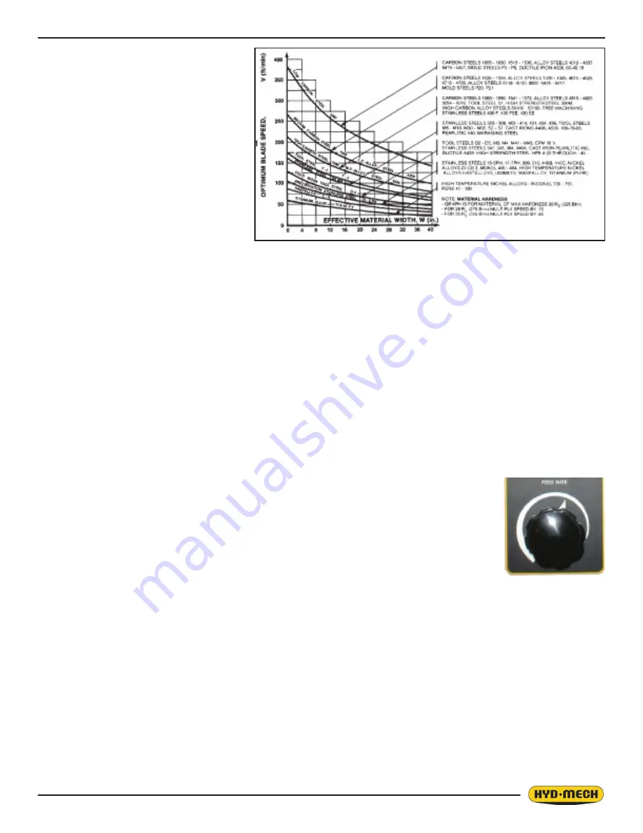
STEP 4, DETERMINE OPTIMUM BLADE
SPEED, V (ft/min) (m/min)
The relationship between optimum blade
speed and effective material width for vari-
ous materials is represented on the graph
shown.
The graph shows that as effective material
width gets wider or as material gets harder,
lower blade speeds are recommended. If
material is narrow or soft, higher blades
speeds should be selected.
In Example #1
•
8” (200mm) diameter #1045 Me-
dium Carbon Steel solid bar is to be
cut.
•
On the graph above find the Medium Carbon Steel Curve which represents the optimum blade speeds for 1045
Carbon Steel.
•
On the horizontal axis (effective material width axis) find number 8 which represents effective material width of an
8” (200mm) diameter solid.
•
Find the point where a vertical line from 8” (200mm) intersects the Medium Carbon Steel Curve.
•
From this intersection point run horizontally left to the vertical axis (optimum blade speed axis) and find the point
marked “200”.
•
For 8” (200mm) diameter, 1045 Carbon Steel solid bar 200 ft/min (60m/min) is the optimum blade speed.
NOTE:
7. Higher than optimum blade speed will cause rapid blade dulling. Lower than optimum blade speeds re-
duce cutting rates proportionately and do not result in significantly longer blade life except where there is
a vibration problem. If the blade vibrates appreciably at optimum speed as most often occurs with struc-
turals and bundles, a lower blade speed may reduce vibration and prevent premature blade failure.
8. Material Hardness - The graph above illustrates blade speed curves for materials of hardness 20 RC
(225 Bhn) or lower. If the material is hardened then the multipliers need to be used. These multipliers are
given in the NOTE at the bottom right of the graph. As the hardness increases the optimum blade speed
decreases.
STEP 5, DETERMINE FEED RATE SETTING, FR (in/min) (mm/min).
FEED RATE is the vertical speed at which the blade descends through the work-piece.
The FEED RATE Knob controls the FEED RATE of the blade descent in the range 0 to 15 in/min
(380mm/min). The FEED RATE should be adjusted only in one direction (from “O” to required
value). If you go too far, go back to “O” and come back up. To set FEED RATE for particular
cutting situations use the Graph below, which represents the relationship between FEED RATE,
blade speed and blade pitch.
For Example #1, it is known from Step 3 that optimum blade pitch is 2/3, and from Step 4 that blade speed, is 200 ft/min
(60mm/min). From the Graph on the left, the FEED RATE is determined in the following way:
•
On the horizontal axis (blade speed axis), find 200 ft/min (60mm/min).
•
Find the point where a vertical line from 200 ft/min (60mm/min) would intersect the 2/3 blade pitch curve.
•
From this intersection point run horizontally left to the vertical (FEED RATE) axis, to arrive at 1.8 in/min (45mm/
min) FEED RATE. Thus 1.8 in/min (45mm/min) is the FEED RATE for cutting 8” (200mm) diameter 1045 Carbon
Steel when the optimum 2/3 pitch blade is used.
If the saw is fitted with a blade coarser than optimum (e.g. 1.4/2.5 TPI) we can still use the graph, but we go to the 1.4/2.5
curve. As a result we find that the FEED RATE is decreased to 1.3 in/min (133mm/min) for this blade. If however, the ma-
chine is fitted with a finer than optimum blade (e.g. 3/4 TPI) we use the graph for the optimum blade as before, and then
use a multiplier given by the table below.
Feed Rate Knob
Содержание H14A
Страница 2: ......
Страница 16: ......
Страница 32: ......
Страница 50: ......
Страница 55: ...4 5 ...
Страница 56: ...4 6 ELECTRICAL SCHEMATICS 208 240 VOLT ...
Страница 57: ...4 7 ...
Страница 58: ...4 8 ...
Страница 59: ...4 9 ...
Страница 60: ...4 10 ...
Страница 61: ...4 11 ...
Страница 62: ...4 12 ...
Страница 63: ...4 13 ...
Страница 64: ...4 14 ...
Страница 65: ...4 15 ...
Страница 66: ...4 16 ...
Страница 67: ...4 17 ...
Страница 68: ...4 18 ELECTRICAL SCHEMATICS 480 575 VOLT ...
Страница 69: ...4 19 ...
Страница 70: ...4 20 ...
Страница 71: ...4 21 ...
Страница 72: ...4 22 ...
Страница 73: ...4 23 ...
Страница 74: ...4 24 ...
Страница 75: ...4 25 ...
Страница 76: ...4 26 ...
Страница 77: ...4 27 ...
Страница 78: ...4 28 ...
Страница 79: ...4 29 ...
Страница 80: ...4 30 ...
Страница 82: ...5 2 GLAND ASSEMBLIES PISTON ASSEMBLIES ...
Страница 83: ...5 3 HYDRAULIC SCHEMATIC ...
Страница 84: ...5 4 HYDRAULIC PLUMBING DIAGRAM ...
Страница 85: ...5 5 ...
Страница 86: ...5 6 ...
Страница 87: ...5 7 ...
Страница 88: ......
Страница 96: ...6 8 FRONT VISE ASSEMBLY ...
Страница 101: ...6 13 ...
Страница 102: ...6 14 BONFIGLIOLI A412 GEARBOX ASSEMBLY ...
Страница 103: ...6 15 ...
Страница 105: ......
Страница 106: ......
Страница 107: ......
Страница 108: ......
Страница 112: ......
Страница 114: ...8 2 H 14A LAYOUT DRAWING ...


