Damocles2
Ares LTE
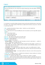
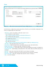
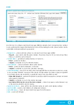
5
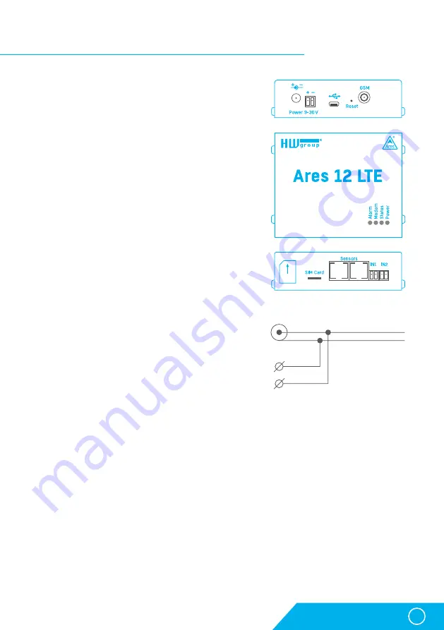
Description of connectors and connections
Identical for Ares 10 LTE.
Description of connectors and connections
LED indicators
•
Alarm (red)
– indicates alarm status. One or more sen-
sors read outside of the allowed range, or an alarm at
one or more inputs (2× Digital Inputs or external power
supply indication).
•
Modem (blue)
– informs about GPRS connection.
•
Fast blinking
– GPRS connection is being established.
•
On
– connection established.
•
Slow / occassional blinking
– communication takes place.
•
Status (yellow)
•
Fast blinking
– GSM connection is being established.
•
Blinking 1× / second
– device works normally.
•
Power (green)
– power is connected. Blinks when the
device runs on battery*.
Inputs
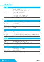
2× Digital Input for connecting a voltage-free (dry) contact.
Logic 0 (contact open) when the resistance between
terminals is greater than 15 kOhm. Logic 1 (closed con-
tact) when the resistance is less than 2.7 kOhm. Resis-
tances between these values are undefined.
Power
Power supply 9-30 V / 500 mA can be connected to the
power terminals or the power barrel connector. The ter-
minals and the connector are interconnected and can
NOT be used to connect two different power sources
(e.g. adapter and back-up battery*).
Sensors
2× independent port for connecting 1-Wire sensors, with support for 1-Wire UNI. Each port can
be connected to a bus, maximum length is 60 m. The total number of supported sensors is
a device-wide limitation, the sensors can be connected to one port or distributed among both
ports in any way.
Caution:
Depending on the consumption of connected sensors the use of an active hub may be necessa-
ry – see chapter 1-Wire UNI Sensors.
Sim Card
Standard Plug-in SIM.
GSM
SMA connector for an external antenna. The external antenna needs to be QuadBand-capable
and equipped with a male SMA connector. External antenna is required for proper operation of
the device.
*Applies to Ares 12 LTE only.
Содержание Ares 10 LTE
Страница 1: ...Ares 10 12 LTE User manual...


