


5
Considering δ=90°, Φ is equivalent to the dielectric loss angle, so it is very simple to evaluate
MOA with Φ; Φ is 81°
to
86° if there is no interphase interference. According to the requirement
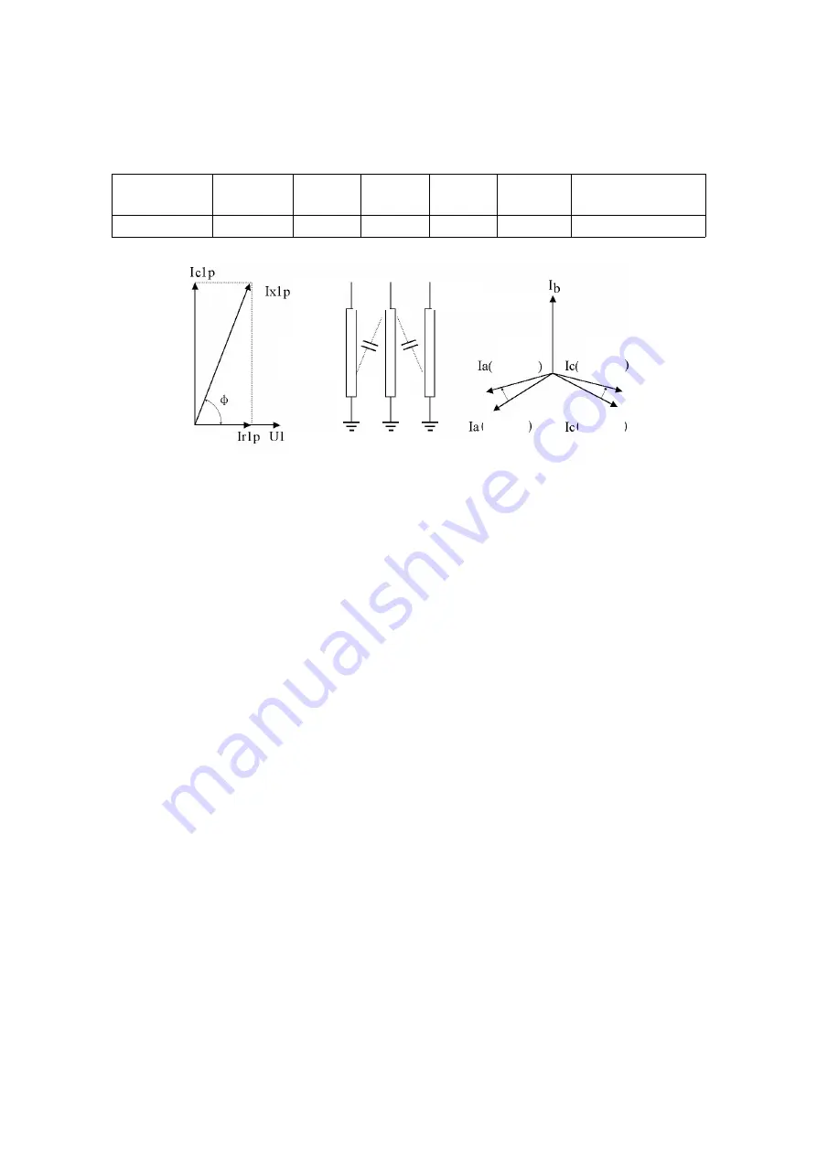
that the resistive current cannot exceed 25% of the total current, Φ cannot be less than 75.5°. refer
to the following table for the segmented evaluation of MOA performance:
Φ
<75°
75°~77
°
78°~80° 81°~83° 84°~88°
>89°
Performance Very poor
Poor
Average
Good
Excellent With interference
In fact, consider in case of Φ<80°
Figure 8 Projection Method
Figure 9 Interphase Interference of In-line Arresters
2.2
Interphase Interference
In the field measurement, the intermediate B phase of the in-line arresters impacts the
leakage currents A and C through the stray capacitance: A phase φ is reduced by 2° or so and the
resistive current is increased; C phase φ is reduced by 2° or so and the resistive current is reduced
to the negative; B phase is not changed. This phenomenon is called interphase interference (Figure
9).
2.3
Performance Evaluation of MOA with Interference
1. It is suggested that the same phase PT secondary voltage should be used to measure the
same phase MOA current. The compensation angle is 0, and the interphase interference is not
considered in the measurement. For the laboratory measurement, the compensation angle (Φ0=0)
should not be used.
The interphase interference can be considered when MOA performance is evaluated. Based on
B phase Φ, the reduced value of A phase Φ is basically equal to the increased value of C phase Φ
according to the symmetry of interphase interference, so as to evaluate the interphase
interference angle. For example, if A phase Φ is 2° less than the normal value, and C phase Φ is 3°
more than the normal value, the interphase interference will be approximately 2.5°. When MOA
performance is evaluated, A is +2.5°, B phase Φ is not changed, and C phase Φ is 2.5°.
2. If the interphase interference is considered in the measurement, the compensation angle
can be set for A/C phase and is added to Φ. Considering the interphase interference of B phase to
A/C phase is symmetrical, if the angle Φca for the leading Ia of Ic is measured, A/C phase will be
respectively compensated, the same phase PT secondary voltage will be used to measure the same
phase MOA current, and the above compensation angle will be added. MOA performance will be
evaluated directly according to Φ.
VII. Precautions:
1. When measure the reference voltage from PT or the measuring end of the testing
transformer, carefully check wiring to avoid the PT secondary or test voltage short circuit.
2. Be careful not to wrongly connect the current and voltage sampling lines in the connecting
process.
3. In the laboratory experiment, the high voltage power supply cannot use the series excitation
testing transformer.
A phase B phase
C phase
Stray
capacitance
With
interference
With
interference
Without
interference
Without
interference


