7-7
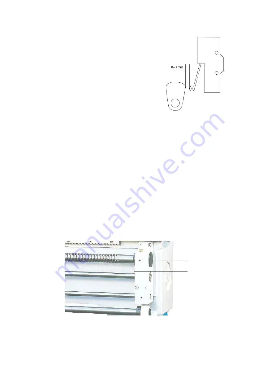
Brake & Micro Switch Adjustment
The foot brake is connected with the
micro switch. There should be 0-1mm
end play between the brake arm and the
head of the micro switch(See Fig. 7-7).
The proper function of the brake is to
first, cut off the power and then engage
the brake belt. After using the brake, it
is necessary to use the control lever to
re-start the lathe.
Fig. 6-7
7-8
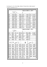
Leadscrew Backlash Adjustment
Should the threading not repeat, the cause is mot likely the leadscrew
backlash. To adjust the backlash, remove the plastic cover on the leadscrew
bracket (Fig. 7-8), loosen nut
○
A
then tighten the left side nut
○
B
. To check
the backlash, engage the half nut and while observing the connecting section
of the leadscrew to the gearbox move the apron handwheel back and forth. If
the backlash is properly set, there should be no movement in the shaft. After
adjusting, re-tighten nut
○
A
and replace plastic cover.
○
A
○
B
Fig. 7-8
34
Содержание HU 480 X 2200 VAC TOPLINE
Страница 1: ...L A T H E MODEL HU 480 X 2200 VAC TOPLINE...
Страница 5: ...1 INVERTER TRANSMISSION LATHE 1 1 Machine Assembly 4...
Страница 33: ...7 4 Lubrication Location A Oil input hole B Oil drain hole 32...
Страница 37: ......
Страница 40: ......
Страница 41: ......
Страница 42: ......
Страница 43: ......
Страница 44: ......
Страница 45: ......
Страница 46: ......
Страница 47: ......
Страница 48: ......
Страница 69: ...BED AND BASE ASSEMBLY ITEM Part Name Amt Model 17 430 Model 19 480 Model 21 530 NO Used Part No Part No Part No...
Страница 75: ...HU 480 x 2200 VAC TOPLINE...
Страница 76: ......


