Hussmann Freedom Line series Скачать руководство пользователя страница 48

4-2


s

tart


up

P/N 0520677_W

U.S. & Canada 1-800-922-1919 • Mexico 1-800-890-2900 • WWW.HUSSMANN.COM

EXPANSION VALVE ADJUSTMENT

Expansion valves on Freedom cases are pre-
adjusted from the factory, but some adjustment 
may be necessary to adjust for specific store 
conditions. Before attempting to adjust valves, 
make sure the evaporator is either clear or 
only lightly covered with frost, and that the 
merchandiser is within 10 deg F (6.5 deg C) of 
its expected operating temperature. Adjust valves 
as follows:

Method 1 (recommended): Attach a sensing 
probe (either thermocouple of thermistor) 
to the evaporator outlet, under the clamp 
holding the expansion valve bulb. Attach 
a pressure probe to the access valve on the 
suction line. Measure superheat by subtracting 
the saturation temperature at the measured 
pressure from the measured outlet temperature. 
Method 2: Attach two sensing probes.

Note: 
When using high glide refrigerants (e.g., 
R-407A, R-448A), use the evaporator pressure 
and subtract the dew point from the coil 
outlet refrigerant temperature to measure the 
superheat level.

Attach two sensing probes (either thermocouple 
or thermistor) to the evaporator. Position one 
under the clamp holding the expansion valve 
bulb; securely tape the other to the coil inlet 
line. 

Some “hunting” of the expansion valve is 
normal. The valve should be adjusted so that 
during the hunting


the


greatest


Difference


between


the


two


probes


is

 3–5 

deg

 f 

(1.7–2.8 

deg

 c).

 With this adjustment, during 

a portion of the hunting the temperature 
difference between the probes will be less than 
3 deg F 

(1.7 

deg

 c) 

and at times 0. 

Make adjustments of no more than 

1

/

4

 turn for 

Balanced Port TEV and 

1

/² turn at a time for 

other valve models. Wait at least 15 minutes 
before re checking the probe temperature or 
making further adjustments.

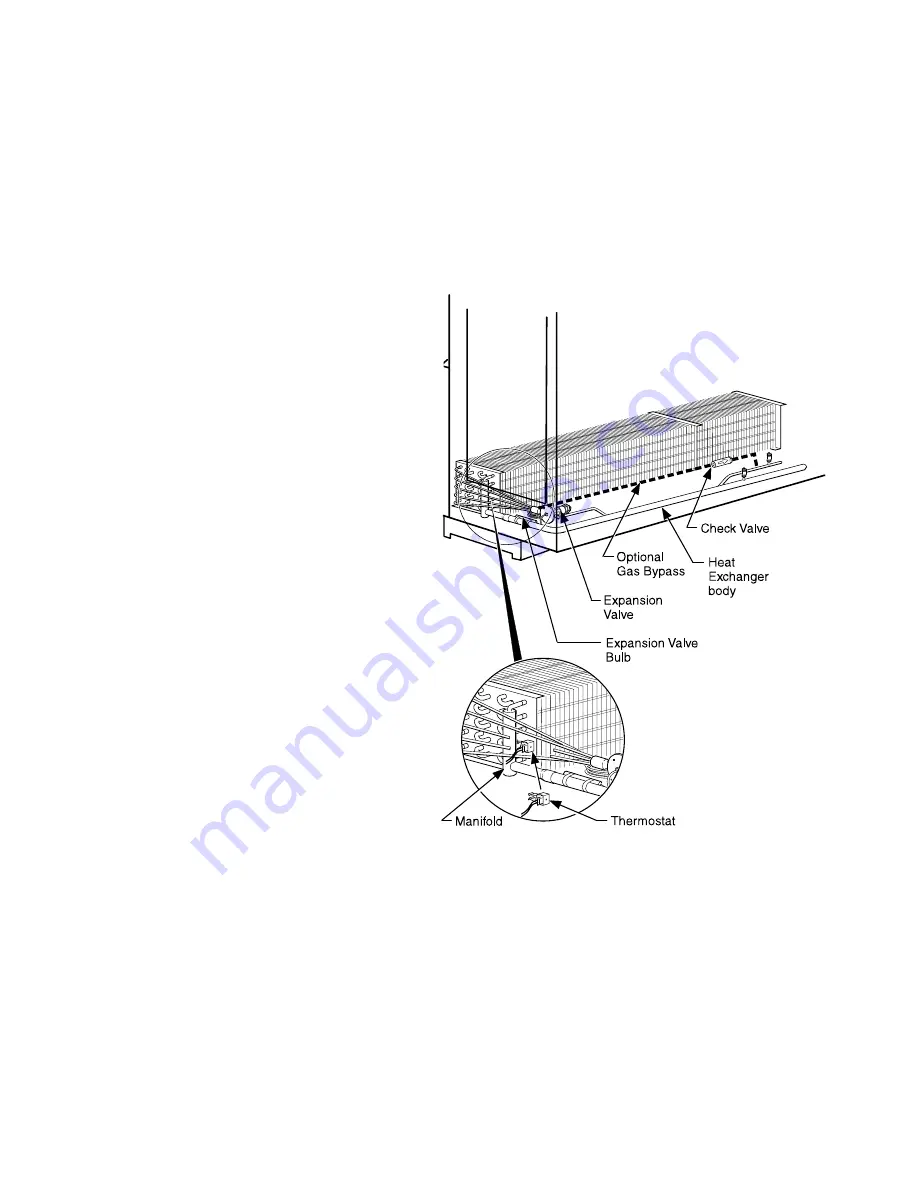
Component Location in 

RL / RM / RLN / 

RLNI Models

Содержание Freedom Line series

Страница 1: ...Case Data Sheets P N 0520677_W June 2021 Spanish P N 0532420 Freedom Line Low or Medium Temperature Compressor Ready Narrow Footprint Reach in Merchandisers IMPORTANT Keep in store for future referenc...

Страница 2: ...mann representative to arrange servicing ANSI Z535 5 DEFINITIONS DANGER Indicate s a hazardous situation which if not avoided will result in death or serious injury WARNING Indicate s a hazardous situ...

Страница 3: ...Lines 2 8 Field Wiring 2 9 Installing Pump Collection Pan Kit 2 10 Installation of Water Lines 2 12 Pre Installation System Cleaning 2 13 Electronic Controller 2 14 Controller Operation 2 16 Controlle...

Страница 4: ...n cludes but is not limited to such itemsasfans heaters thermostats and lights Do not use mechanical devices or other means to accelerate the defrosting process Do not use electrical appliances inside...

Страница 5: ...er cooled condensing unit They are controlled by an electronic control The case temperature is controlled by cycling the compressor based on the discharge air temperature input The sensor for this inp...

Страница 6: ...arrier will provide any necessary inspection reports and or claim forms Apparent Loss Or Damage If there is an obvious loss or damage it must be noted on the freight bill or express receipt and signed...

Страница 7: ...th the case s can be used to bring the merchandiser into the store and place it to its final location MOVING MERCHANDISER THROUGH NARROW STORE ENTRANCES Some exterior merchandiser parts may be disasse...

Страница 8: ...3 Remove Lower Front Panel Remove the front panel as follows remove screws from front panel tabs then lift the front panel Refer to the illustration below 4 Remove the screws that attach the wireway...

Страница 9: ...9 The splashguard panels and case facade can be removed from the top of the case to provide clearance for door openings 10 Remove the piping cover plate from the top of the case 6 screws 11 Pull the...

Страница 10: ...sing care to ensure all panels are centered and properly fastened Be sure to replace all screws and secure all components The condensing unit produces vibration that can cause screws to loosen LEVELIN...

Страница 11: ...ined in line yielding one long continuous display requiring only one pair of ends Joining kits and instructions are shipped with each merchandiser To join like fixtures a joining kit is required To jo...

Страница 12: ...s been leveled according to the main installation instruction Carefully unpack and inspect the joining parts listed above to verify completeness and that there is no damage 1 Prepare cases for joining...

Страница 13: ...rom ends to be joined by lifting up and out near the bottom No tools are necessary F Remove joint molding from any door frames that will be joined to another case G RFLNI Only Remove screws and interi...

Страница 14: ...t of the cases in the line up The front base frame should be on the chalk line 3 Once cases are close to final place ment remove the shipping braces from the ends to be joined see Figure 3 Discard bol...

Страница 15: ...Line Reach in 4 If not already installed make sure Nut Retainers and Alignment Pins are in place in the right end frame as shown in Figure 4A or 4B Figure 4 Verify Nut Retainer Installation RFL RFLN...

Страница 16: ...shown on next page Figure 5A Apply Gasket to Left End RFL RFLN F R O N T Right End Left End F R O N T 1 Donut 2 1 in x in 3 in x in Use all three gaskets When applying an end assembly Left End Case F...

Страница 17: ...as Shown 1 2 3 Detail A 1 2 3 Donut Gasket Foam 906 inch x 1 2 inch x 200 inch Foam 1 2 inch x 1 4 inch Right End Case to Case Joint or End Panel Apply Donut Gasket Foam Gaskets and Gasket Pad to Rig...

Страница 18: ...1 14 Installation P N 0520677_W U S Canada 1 800 922 1919 Mexico 1 800 890 2900 WWW HUSSMANN COM Figure 6A Apply Gaskets RFLNI Left End Case Gasket Pad Donut Gaskets Must Be Applied As Shown...

Страница 19: ...S A Freedom Line Reach in 1 in x in in x in Figure 6B Apply Gaskets to Right End RFLNI Right End Case Gasket Pad Donut 1 in x in in x in Gaskets Must Be Applied As Shown Make sure area where raceway a...

Страница 20: ...second merchandiser against first mating alignment pins with corresponding holes Use care when pushing the cases together RFL RFLNI Do not cut wires routed along the front bumper retainer See detail i...

Страница 21: ...ack position and join 2 places C Join at the top front position D Go to the middle back wall position and join E Join at the lower back wall F Finally join at the top back wall position Following the...

Страница 22: ...677_W U S Canada 1 800 922 1919 Mexico 1 800 890 2900 WWW HUSSMANN COM A R LNI A E B 6 5 F D C Alignment Pin Alignment Pin Nut Retainer RFLNI Figure 7C Joining Sequence for RFLNI Cases Alignment Pin A...

Страница 23: ...e length of the line up Do NOT install the last bumper sections at this time These sections will be installed in the last step Once all except the last section of bumper have been installed refrigerat...

Страница 24: ...1 20 Installation P N 0520677_W U S Canada 1 800 922 1919 Mexico 1 800 890 2900 WWW HUSSMANN COM NOTES...

Страница 25: ...ally if a leak is suspected Read all safety information regarding the safe handling of refrigerant and refrigerant oil including the Material Safety Data Sheet MSDS sheets can be obtained from your re...

Страница 26: ...s located above the next to last door on the right facing the case After mounting the condensing unit the electrical box and must be re attached to the top The condensate pan if provided is packed ins...

Страница 27: ...N HIDDEN LINES FOR CLARITY A NUT J RETAINER TOP CON TO BE OPE WI SCREW CAP 5 16 3 4 LOCKWSHR 5 1 STL WASHER FLAT 5 1 NARROW NUT J RETAINER CONDENSING UN SUPPORT HMDSL EXPLODED VIEW TO SHOW CONDENSING...

Страница 28: ...X 5 FT 75 NPTF X 0 75 NPSM CONDENSING UNIT TOP PIPING LINE CONNECTIONS Locate the packout bag from inside of the case The packout kit contains Filler Foam Silicone Butyl Tape Insulation pre slit 7 8...

Страница 29: ...k Connect couplings If necessary carefully wipe coupling seats and threaded surfaces with a clean cloth to prevent the inclusion of dirt or any foreign material in the system Lubricate male half diaph...

Страница 30: ...pierce the diaphragms on each coupling half If the nut will not start by hand adjust the position of the line set to ensure proper coupling alignment and eliminate minimize all side load force on the...

Страница 31: ...ection Continued from Page 2 4 4 Insert foam filler into slot Ensure there are no gaps around foam filler Place silicone around the tubing 4 Foam Filler 6 7 5 Replace bracket Ensure insulation is on t...

Страница 32: ...on extra insulation is provided to cover the field connected tubing sections These exposed sections must be covered with insulation Check that all suction lines are adequately covered with insulation...

Страница 33: ...minal blocks are located inside the electrical box on top of the case The wiring diagram and circuit requirements are provided on the Technical Data Sheets provided with the case and condensing unit A...

Страница 34: ...ater to the condensate pan on top of the case Evaporation pan must be installed level and plugged into electrical receptacle The tubing should be inspected through its entire length to ensure that it...

Страница 35: ...talled Tee Pump Discharge Line Case Wire Whip 3 photo for reference 4 5 6 3 Replace cover plates 4 Connect tubing to pump 5 Place pan and pump under case 6 Connect tubing to condensate pan NOTE 6A 2 3...

Страница 36: ...be supplied Refer to the techncial data sheets for flowrate pressure drop and heat of rejection Water supply must have adequate corrosion inhibitors and freeze protection Refer to Document 0525699 for...

Страница 37: ...consult and be familiar with the manufacturer s Material Safety Data Sheets MSDS before handling any secondary fluid The MSDS contains proper disposal and safety methods Automatic Balancing Valves Ca...

Страница 38: ...ith the Emerson Electronic Unit Controller including water cooled units the high and low pressure safety controls are connected to terminals 18 and 19 of the XR75 case controller Air cooled unit have...

Страница 39: ...alarm may be silenced by pressing any of the buttons on the front of the controller display Possible causes of high low pressure alarm Excessive refrigerant Lack of refrigerant Lack of air flow into t...

Страница 40: ...ng mode or to confirm an operation Starts a manual defrost Press the UP arrow to see the MAX tempera ture to browse the parameter codes in pro gramming mode or to increase the currently displayed temp...

Страница 41: ...ipment Mount control display to lineup with cutout in fascia panel CONTROLLER BOX RUN SENSOR LEADS FROM HANDY BOX TO CONTROLLER BOX IN CONDUIT 9 00 6 00 MOUNT CONTROLLER BOX HERE FOR SHIPPING B B RUN...

Страница 42: ...Sensor located on the bottom row return bend closest to the center of the coil A Safe NET sensor location A controller sensor location Discharge air sensor is located at front of case Defrost Terminta...

Страница 43: ...Case using Self Drilling screws every 2 feet Vertical Supports INSTALL FACADE Install facades on case lineup using supplied hardware Note location s of controller box in facade cutout for the various...

Страница 44: ...T place shims under splashguard brackets INSTALLING SPLASHGUARDS The splashguard is shipped inside each merchandiser After merchandisers have been leveled and joined and all drip piping electrical and...

Страница 45: ...nal stainless steel splashguards may be sealed to the floor using a vinyl cove base trim The size of trim needed will depend on how much the floor is out of level To install the trim to the splashguar...

Страница 46: ...set across joints Make sure that no gaps exist between sections Continue installing bumpers the length of the line up Do NOT install the last bumper sections at this time These sections will be instal...

Страница 47: ...rs before loading product Regularly check merchandiser temperatures Do not break the cold chain Keep products in coolerorfreezerbeforeloadingintomerchandiser Medium temperature merchandisers are desig...

Страница 48: ...red outlet temperature Method 2 Attach two sensing probes Note When using high glide refrigerants e g R 407A R 448A use the evaporator pressure and subtract the dew point from the coil outlet refriger...

Страница 49: ...Once the case is considered ready for start up move the main switch on the electrical box to the on position This switch is located on the front of the electrical box on the top of the case This toggl...

Страница 50: ...ure should be less than 10 above water inlet temperature Verify that the fans are running The fans will be off if the case is in a defrost cycle They will come back on after the completion of this cyc...

Страница 51: ...on of product during stocking is necessary to prevent product loss Always bring the oldest product to the front and set the newest to the back Air discharge and return flues must remain open and free...

Страница 52: ...disers Price Tag Molding Suggested Mounting Locations in Single Deck Glass Front Impact Merchandisers Package Guard Facing Out Hussmann P N 0429971_C 10 2007 Double Stick Tape Flexible Plastic Fits in...

Страница 53: ...The thermometer may need to be moved several times to find the warmest location Mounting options include flexible plastic for price tag molding application magnet applied to back of flexible plastic f...

Страница 54: ...4 8 Start up P N 0520677_W U S Canada 1 800 922 1919 Mexico 1 800 890 2900 WWW HUSSMANN COM NOTES...

Страница 55: ...rior surfaces Ammonia based cleaners on acrylic surfaces Do Remove the product and all loose debris to avoid clogging the waste outlet Store product in a refrigerated area such as a freezer Remove onl...

Страница 56: ...ry after wetting Use alkaline chlorinated or non chlorine containing cleaners such as window cleaners and mild detergents Do not use cleaners containing salts as this may cause pitting and rusting of...

Страница 57: ...Cleaning None Cleaning None Replacement Replacement 1 1 12 6 4 4 N A 6 N A 0 2 0 2 2 0 05 0 1 0 1 0 1 0 2 N A 0 05 N A 1 1 2 0 05 1 2 0 6 0 4 0 8 N A 0 03 N A 0 2 0 2 This table is provided for refer...

Страница 58: ...ottom The Heated Evaporation Pans are located on the case top Evidence of excess water or odor is an indication that immediate service is required Recommended cleaning the Condensate Pump reservoir an...

Страница 59: ...arness 9 Turn on power 10 Verify that motor is working and blade is turning in the correct direction 11 Close air gaps under fan plenum Warmer air moving into refrigerated air reduces effective coolin...

Страница 60: ...wer fan plenum 8 Turn on power 9 Verify that heater is working correctly 10 Close air gaps under fan plenum Warmer air moving into refrigerated air reduces effective cooling If the plenum does not res...

Страница 61: ...y The drain pan heater is located as shown below Remove Drain Pan Heater 1 Disconnect power 2 Pull heater out from under jiffy clips 3 Position new heater under jiffy clips Be sure offset is properly...

Страница 62: ...anufacturer REPAIRING ALUMINUM COIL The aluminum coils used in Hussmann merchandisers may be easily repaired in the field Materials are available from local refrigeration wholesalers Hussmann recommen...

Страница 63: ...in any one drip pipe Double water seals in series will cause an air lock and prevent draining Pitch the drip piping in the direction of flow There should be a minimum pitch of 1 4 in per ft 20 mm per...

Страница 64: ...e trap to the floor as shown NOTE It may be necessary to rotate water seal trap inside the tee a few degrees to ensure clearance at two locations There must be clearance 1 between the bottom of the wa...

Страница 65: ...our full rotations 6 Installed drip piping may require additional support depending on the number and location of the hub floor drains The installer should always provide adequate support to all drip...

Страница 66: ...information or other support contact your Hussmann representative Please include the model and serial number of the product Hussmann Corporation Corporate Headquarters Bridgeton Missouri U S A 63044 2...

Отзывы: