background image

8

General Operation

• DO 

NOT 

operate mower with collection system, unless the 

front weights are installed. Read, understand and follow all 

instructions in the manual and on the machine before starting.

•  Keep machine free of grass, leaves or other debris buildup 

which can touch hot exhaust/engine parts and burn. Do not 

allow the mower deck to plow leaves or other debris which 

can cause buildup to occur.

•  Stop engine before removing collection system or unclogging 

chute.

•  Do not operate the mower without either the entire collection 

system or the guard in place. Be aware of the mower discharge 

direction and do not direct it towards anyone.

•  Clear the area of objects such as rocks, stones, toys, wire 

etc., which could be picked up and thrown by the blades.

•  Only allow responsible adults, who are familiar with the 

instructions, to operate the machine.

•  The owner and operator of this equipment can prevent 

accidents and is responsible for accidents or injuries occurring 

to themselves, other people and/or property.

•  Be sure the area is clear of all people and pets before mowing. 

Stop the machine if anyone enters the area.

•  Never carry passengers or children even with blades o

 .

•  Do not mow in reverse unless absolutely necessary. Always 

look down and behind before and while backing.

•  Slow down before turning.
•  Never leave the machine unattended when the engine is 

running. Always turn o

  the blades, set the parking brake, stop 

the engine and remove the key before leaving the machine.

• Turn 

o

  blades when not mowing.

•  Mow only in daylight or good arti

fi

 cial light.

•  Do not operate the machine while under the in

fl

 uence  of 

alcohol or drugs.

•  Watch out for tra

  c when operating near or crossing roadways.

•  Use extra care when loading and unloading the machine onto 

a trailer or truck.

•  Data indicates that operators, age 60 years and above, are 

involved in a large percentage of riding mower-related injuries. 

These operators should evaluate their ability to operate the 

riding mower safely enough to protect themselves and others 

from serious injury.

•  Clean any oil or fuel spillage before operating or storing the 

machine.

•  Allow machine to cool before storage.

Slope Operation

  WARNING! Maximum recommended operating 

angle of mower with a collection system is 10°.

Slopes are a major factor related to loss-of-control and tip-over 

accidents, which can result in severe injury or death. All slopes 

require extra caution. If you cannot back up the slope or if you 
feel uneasy on it, do not mow it.

DO

•  Mow up and down slopes (10° Max.), not across.
•  Remove obstacles such as rocks, tree limbs, etc.
•  Watch for holes, ruts, or bumps. Uneven terrain could overturn 

the machine. 

Tall grass can hide obstacles.

•  Use slow speed. Choose a low speed so that you will not have 

to stop while on the slope.

•  Use extra care with collection systems or other attachments. 

These can change the stability of the machine.

•  Keep all movement on the slopes 

slow 

and 

gradual.

 Do not 

make sudden changes in speed or direction.

•  Avoid starting or stopping on a slope. If tires lose traction, 

disengage the blades and proceed slowly 

straight

 down the 

slope.

DO NOT

• Do 

not

 turn on slopes unless necessary, and then, turn slowly 

and gradually downhill, if possible.

• Do 

not 

mow near drop-o

 , ditches, or embankments. The 

mower could suddenly turn over if a wheel is over the edge 

of a cli

  or ditch, or if an edge caves in.

• Do 

not

 mow on wet grass. Reduced traction could cause 

sliding.

• Do 

not

 try to stabilize the machine by putting your foot on the 

ground.

Service

•  Collection system components are subject to wear, damage, 

and deterioration, which could expose moving parts or allow 

objects to be thrown. Frequently check components and 

replace with manufacturer’s recommended parts, when 

necessary.

•  The operation of any mower can result in foreign objects 

thrown into the eyes, which can result in severe eye damage. 

Always wear safety glasses or eye shields while operating the 

mower or performing any adjustments or repairs. A wide vision 

safety mask over spectacles or standard safety glasses are 

recommended.

•  Keep nuts and bolts, especially blade attachment bolts, tight 

and keep equipment in good condition.

•  Never tamper with safety devices. Check regularly for proper 

operation.

•  Keep machine free of grass, leaves, or other debris buildup. 
•  Clean oil or fuel spillage. 
•  Allow machine to cool before storing.
•  Stop and inspect the equipment if you strike an object. Repair, 

if necessary, before restarting.

•  Never make adjustments or repairs with the engine running.
•  Mower blades are sharp and can cut. Wrap the blade(s) or 

wear gloves, and use extra caution when servicing them.

•  Check brake operation frequently. Adjust and service as shown 

in the Operator Manual.

Towing

•  Tow only with a machine that has a hitch designed for towing. 

Do not attach towed equipment except at the hitch point.

  WARNING!

  THIS CUTTING MACHINE IS CAPABLE 

OF AMPUTATING HANDS AND FEET AND THROWING 
OBJECTS. FAILURE TO OBSERVE THE FOLLOWING 
SAFETY INSTRUCTIONS COULD RESULT IN SERIOUS 
INJURY OR DEATH.

SAFETY

Содержание Z400 COLLECTION SYSTEM

Страница 1: ...las instrucciones correspondientes antes de utilizar la máquina Manuale di istruzioni Leggereattentamenteleistruzionidelmanu ale del rasaerba e accertarsi di averle com prese prima di utilizzare questa macchina Instructieboekje Lees de instructies in de bedieningshandle iding van de maaier zorgvuldig door en zorg ervoor dat u de instructies hebt begrepen voordat u de machine in gebruik neemt Z400 ...

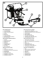
Страница 2: ...ICHTE 5 LEITBLECHE 6 KUPPLUNGSPLATTE 7 LAUBBLASGERÄT 8 WELLROHR 9 BEUTELBEHÄLTER IDENTIFICAZIONE DELLE PARTI 1 COMPLESSIVO COPERCHIO 2 SUPPORTO RACCOGLIERBA 3 STAFFA DI MONTAGGIO DEL CONTRAPPESO 4 PESI 5 DEFLETTORI 6 PIASTRA DI ATTACCO 7 COMPLESSIVO SOFFIATORE 8 COMPLESSIVO TUBO CORRUGATO 9 CONTENITORI DI SACCHETTI IDENTIFICATION DES PIÈCES 1 CAPOT 2 SUPPORT DE COLLECTEUR 3 SUPPORT DE FIXATION DE ...

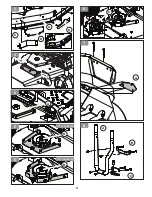
Страница 3: ...3 3 2 C B A D A 4 C 6 A 7 B C A 8 B 5 137 cm 54 in B 5 152 cm 60 in ...

Страница 4: ...4 D E F 10 G 11 G H 12 I J K 13 A B 14 C 15 9 ...

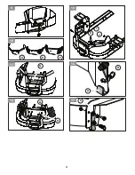
Страница 5: ...5 16 17 18 D 19 A B 20 C 21 A B 22 C 23 ...

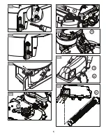
Страница 6: ...6 A B C 29 3 18 cm 1 25 in 25 Z400 26 A B E D C 27 F 28 10 11 12 1 2 3 4 5 6 7 8 9 24 ...

Страница 7: ...horized distributors and dealers therefore all requests for parts and service should be directed to your local dealer s Our philosophy is to continually improve all of our products If the operating characteristics or the appearance of your product differs from those described in this Manual please contact your local dealer for updated information and assistance For TechnicalAssistance visit the bra...

Страница 8: ...ion If you cannot back up the slope or if you feel uneasy on it do not mow it DO Mow up and down slopes 10 Max not across Remove obstacles such as rocks tree limbs etc Watch for holes ruts or bumps Uneven terrain could overturn the machine Tall grass can hide obstacles Use slow speed Choose a low speed so that you will not have to stop while on the slope Use extra care with collection systems or o...

Страница 9: ... trash bags when full a Disengage blades place motion control lever s in neutral position engage the parking brake stop the engine and dismount unit Raise seat forward on tractor models b Unlatch and raise cover c Remove one container at a time by grasping container handles and pulling toward the rear off of the tube rails d With the container resting on the ground close and secure the top of the p...

Страница 10: ...when you are seated on the mower in the operator s position Container Contents Corrugated Tube Assembly Bag containers Baffles Collector mount Cover Assembly Bags of Hardware Blower Assembly Drive Pulley Belt Shield Weight Mounting Bracket Weights Belt INSTALLING BLOW OUT BAFFLES NOTE The collection system includes optional deck baffling designed to help prevent blow out when collecting in extremely d...

Страница 11: ...ch the tube assembly to the machine at the upper mount B and spacer plate G between the rear guard and upper mount bracket B with three 5 16 18 x 1 1 4 hex head flange bolts Fig 11 Models with Rear Guard E 4 Attach the tube assembly to the machine at the upper mount B and three spacers tubes H between the Rear Guard with spacer plate G on the inside of the Rear Guard with three 5 16 18 x 1 1 2 hex...

Страница 12: ... pattern shown starting at the bottom right hole and alternating every other hole until all screws are installed then torque to 1 69 2 25 Nm 15 20 in lb Fig 24 5 Install front of corrugated tube to the blower If hose is too long when deck is positioned in the lowest cut position the hose can be rotated in a counterclockwise direction left hand threads to reduce slack and trimmed from the inside of...

Страница 13: ...rn hose end to end X Rotate hose X Clean machine X Maintenance Schedule The machine is heavy and can cause serious crushing injuries Be extra cautious when it is loaded on or unloaded from a vehicle or trailer Use an approved trailer to transport the machine Activate the parking brake turn off the fuel supply and fasten the machine with approved fastening devices such as bands chains or straps Chec...

Страница 14: ...e vom Hersteller empfohlenen Teile WARNUNG DIESE MÄHMASCHINE KANN HÄNDE UND FÜSSE AMPUTIEREN UND OBJEKTE UMHERSCHLEUDERN DAS NICHTBEACHTEN DER FOLGENDEN SICHERHEITSHINWEISE KANN ZU VERLETZUNGEN ODER ZUM TOD FÜHREN WIR GRATULIEREN IHNEN zum Kauf Ihres neuen Sammelsystems Es wurde so konzipiert konstruiert und hergestellt dass es optimale Zuverlässigkeit und Leistung bietet Wir bieten über autorisie...

Страница 15: ...eln auf und abwärts max 10 aber nie quer zum Hang Entfernen Sie Hindernisse wie Steine Äste usw WARNUNG DER EMPFOHLENE MAXIMALWINKEL FÜR DEN BETRIEB EINES MÄHERS MIT SAMMELSYSTEM IST 10 Achten Sie auf Löcher Furchen oder Bodenwellen Bei unebenem Boden könnte die Maschine kippen Hohes Gras kann Hindernisse verbergen Mähen Sie mit geringer Geschwindigkeit Wählen Sie eine geringe Geschwindigkeit soda...

Страница 16: ...as Element abnehmen Bei Traktormodellen muss der Sitz nach vorne gekippt werden b Lösen und heben Sie die Abdeckung an c Entfernen Sie die Behälter nacheinander indem Sie die Griffe der Behälter fassen und nach hinten ziehen weg von den Rohrführungen d Während der Behälter auf dem Boden steht schließen und sichern Sie die Oberseite des Plastiksacks e Neigen Sie den Behälter zur Seite und ziehen Sie...

Страница 17: ...s Schneidwerk in die unterste Schnittposition ab 3 Entfernen Sie den Vorsatz oder die Schraube mit einem 1 2 Zoll Schraubenschlüssel von der rechten Auswurf Seite der Antriebsabdeckung und entfernen Sie diese vom Schneidwerk Lösen Sie die Spannung vom Schneidwerkriemen und entfernen Sie ihn von der mittleren Schneidwerk Riemenscheibe HINWEIS Halten Sie die Scheibenabdeckung für nach der Entfernung...

Страница 18: ...en Sie die Vorderenden der Montagebügel mit 5 16 18 x 1 Zoll Schlossschrauben und Muttern an den Tankhalterungen Abb 13 7 Um zu verhindern dass die Bügel die EMF Electronic Fuel Management Box des Motors oder andere kritische Komponenten berühren platzieren Sie den Schaumstreifen K auf der Innenseite des Bügels nachdem Sie die Oberfläche von Gras und Verschmutzungen befreit haben So verhindern Sie...

Страница 19: ...lsystem nutzen muss die Handbremse auf 3 18 cm 1 25 Zoll in der aktivierten Position eingestellt werden 1 Stellen Sie den Mäher auf einer ebenen Fläche ab 2 Ziehen Sie die Handbremse an 3 Halten Sie mit einer Zange das Bremskabel A in der angezeigten Position fest Abb 29 3 Lösen Sie mit einem 1 2 Zoll Schraubenschlüssel die Gegenmutter B 4 Drehen Sie die 5 16 Zoll Feststellmutter C mit einem 1 2 Z...

Страница 20: ...t einem dafür zugelassenen Anhänger Aktivieren Sie die Handbremse drehen Sie die Kraftstoffzuleitung ab und befestigen Sie die Maschine mit dafür zugelassenen Vorrichtungen wie z B Gurte Ketten oder Bänder Informieren Sie sich über diesbezügliche Vorschriften in der betreffenden Straßenverkehrsordnung bevor Sie die Maschine auf der Straße transportieren Laden Sie die Maschine mithilfe von Rampen mit...

Страница 21: ...andées par le fabricant APPRENEZ À CONNAÎTRE VOTRE SYSTÈME DE RAMASSAGE LISEZ ATTENTIVEMENT CE MANUEL D INSTRUCTIONS ET LES RÈGLES DE SÉCURITÉ AVANT DE MONTER OU D UTILISER VOTRE SYSTÈME DE RAMASSAGE Comparez les illustrations avec le contenu du carton pour vous familiariser avec les pièces avant de commencer le montage Étudiez soigneusement les instructions d utilisation et les précautions de séc...

Страница 22: ...Utilisation dans des terrains en pente La conduite en pente est l une des opérations présentant le plus grand risque de perte de contrôle ou de retournement de la machine et pouvant causer des blessures graves voire la mort Redoublez de prudence sur tout terrain en pente Si vous ne pouvez pas monter la pente en marche arrière ou si vous n êtes pas à l aise ne tondez pas la pente À FAIRE Tondez dan...

Страница 23: ...issant les poignées du conteneur et en tirant vers l arrière hors des rails du tube d Posez le conteneur au sol puis fermez et fixez le haut du sac en plastique e Basculez le conteneur et faites glisser le sac plein hors du conteneur f Installez un nouveau sac à gazon en plastique en plaçant les bords du sac par dessus le bord supérieur des conteneurs g Répétez l opération pour les autres conteneu...

Страница 24: ...lecteur Capot Sacs de matériel Ensemble du souffleur Poulie motrice Carter de la courroie Support de fixation de contrepoids Contrepoids Courroie INSTALLATION DES DÉFLECTEURS D ÉVACUATION REMARQUE le système de ramassage comprend un système de déflecteurs en option conçu pour empêcher la rupture lors du ramassage dans des conditions de coupe extrêmement sèches En cas de coupe dans des conditions ext...

Страница 25: ...de montage aux supports du réservoir de carburant avec des boulons de carrosserie de 5 16 18 x 1 et des écrous Fig 13 7 Pour éviter tout contact des sangles de support avec le boîtier de gestion électronique du carburant EFM sur le moteur ou d autres composants essentiels placez la bande de mousse K sur l intérieur de la sangle après avoir nettoyé la graisse ou les débris présents sur la surface a...

Страница 26: ...à tête hexagonale de 13 16 x 3 4 sur l avant de la partie supérieure du bac dans l adaptateur du tube ondulé selon le schéma de serrage indiqué en commençant par le trou inférieur droit et en alternant chaque autre trou jusqu à ce que toutes les vis soient installées puis serrez à un couple de 1 69 2 25 Nm 15 20 po lb Fig 24 5 Posez l avant du tube ondulé sur le souffleur Si le tuyau est trop long l...

Страница 27: ...ue Utilisez une remorque approuvée pour le transport de la machine Serrez le frein de stationnement fermez l alimentation en carburant et attachez la machine avec des dispositifs de fixation approuvés tels que des courroies des chaînes ou des sangles Renseignez vous sur la réglementation de la circulation locale avant le transport sur route et respectez la Chargez l unité sur un camion ou une remo...

Страница 28: ...ricante ENHORABUENA por adquirir un sistema de recogida nuevo Se ha diseñado desarrollado y fabricado para ofrecer lo máximo en términos de rendimiento y fiabilidad Ofrecemos piezas servicio y mantenimiento en nuestra red de distribuidores autorizados por consiguiente debe efectuar todas sus solicitudes de piezas y tareas de servicio y mantenimiento en sus distribuidores locales Nuestra filosofía ...

Страница 29: ...da puede esconder obstáculos Utilice una velocidad lenta Seleccione una velocidad baja para no tener que parar en la pendiente Proceda con especial precaución cuando utilice sistemas de recogida y otros accesorios Pueden afectar a la estabilidad de la máquina En las pendientes realice todos los movimientos de manera lenta y gradual No realice cambios súbitos de velocidad ni dirección Evite arranca...

Страница 30: ... posición neutra active el freno de estacionamiento detenga el motor y desmonte la unidad En aquellos modelos que cuenten con tractor levante el asiento hacia delante b Desenganche y levante la cubierta c Retire los contenedores uno a uno Para ello agarre las asas del contenedor y tire de ellas hacia atrás en sentido opuesto a las guías del tubo d Una vez el contenedor esté apoyado sobre el suelo ...

Страница 31: ...El sistema de recogida incluye unos deflectores opcionales para el equipo diseñados para evitar explosiones al usarlo en condiciones extremadamente secas Si las condiciones de corte no son extremadamente secas los deflectores no son necesarios Fig 2 NOTA No apriete la tornillería hasta que se le indique que debe hacerlo 1 Retire la tornillería del deflector central del equipo 2 Coloque el deflecto...

Страница 32: ...os Seguidamente continúe con las instrucciones para modelos con protección trasera D que se indican más adelante Modelos con protección trasera D 4 Monte el conjunto del tubo en la máquina en el soporte superior B y la placa separadora G entre la protección trasera y el soporte superior B con tres pernos de brida de cabeza hexagonal de 5 16 18 x 1 1 4 Fig 11 Modelos con protección trasera E 4 Mont...

Страница 33: ...amente apriételos a 1 69 2 25 Nm 15 20 pulgadas libra Fig 24 5 Monte la parte delantera del tubo corrugado en el soplador Si la manguera fuera demasiado larga con el equipo colocado en la posición de corte más baja es posible girarla hacia la izquierda roscas a izquierdas para reducir la holgura y acortarla desde el interior de la parte superior del recortadora 6 Fije el tubo corrugado al conjunto...

Страница 34: ... remolque Utilice únicamente remolques homologados para transportar la máquina Ponga el freno de estacionamiento apague el suministro de combustible y sujete la máquina con dispositivos de sujeción homologados como cintas cadenas o correas Consulte y cumpla las normas locales de tráfico cuando transporte la máquina por cualquier vía Cargue la unidad en un camión o remolque utilizando rampas lo suf...

Страница 35: ...bi raccomandati dal produttore CONGRATULAZIONI per l acquisto di un nuovo sistema di raccolta Il prodotto è stato ideato progettato e realizzato per garantire la massima affidabilità e le migliori prestazioni Forniamo ricambi e assistenza tramite la nostra rete di distributori e rivenditori autorizzati pertanto tutte le richieste di ricambi e assistenza devono essere indirizzate ai rivenditori local...

Страница 36: ...ostacoli Procedere a velocità ridotta Procedere a velocità moderata in modo da non doversi fermare sui pendii Prestare la massima attenzione quando si utilizzano i sistemi di raccolta o altri accessori in grado di modificare la stabilità della macchina Procedere sempre a velocità uniforme e moderata sui pendii Non effettuare bruschi cambiamenti di velocità o di direzione di marcia Non avviare o arr...

Страница 37: ...o pieni a Disinnestare le lame portare le leve di comando del movimento in posizione neutra inserire il freno di stazionamento arrestare il motore e smontare l unità Sollevare il sedile in avanti sui modelli con operatore a bordo b Sbloccare e sollevare il coperchio c Rimuovere dalle guide del tubo un contenitore alla volta afferrando le impugnature e tirando verso la parte posteriore d Con il cont...

Страница 38: ... soffiatore Puleggia di trasmissione Pannello cinghia Staffa di montaggio del contrappeso Contrappesi Cinghia INSTALLAZIONE DEI DEFLETTORI DI SCARICO NOTA il sistema di raccolta include dei deflettori opzionali per il piatto progettati per impedire il soffiaggio di aria durante la raccolta in condizioni estreme di taglio a secco Se le condizioni di taglio non sono eccessivamente secche i deflettori pot...

Страница 39: ...ione posteriore se non sono presenti fori quindi attenersi alle istruzioni riportate di seguito per i modelli con protezione posteriore D Modelli con protezione posteriore D 4 Fissare il complessivo del tubo alla macchina sul supporto superiore B e sulla piastra distanziatrice G tra la protezione posteriore e la staffa del supporto superiore B con tre bulloni flangiati a testa esagonale da 5 16 18 ...

Страница 40: ...ella parte superiore del raccoglierba attraverso l apertura Fig 23 4 Utilizzando una chiave a cricchetto con una bussola da 5 16 montare le dodici viti a testa esagonale da 13 16 x 3 4 attraverso la parte anteriore superiore del raccoglierba nell adattatore del tubo corrugato secondo lo schema di serraggio mostrato a partire dal foro inferiore destro e alternando ogni due fori fino a quando non ve...

Страница 41: ...to da veicoli o rimorchi Utilizzare un rimorchio apposito per il trasporto della macchina Azionare il freno di stazionamento arrestare l alimentazione di carburante e fissare la macchina mediante dispositivi di fissaggio appropriati quali funi catene o corde Prima di trasportare la macchina su strada verificare le disposizioni legislative locali Caricare l unità sull autocarro o rimorchio conducen...

Страница 42: ...ang deze indien nodig door onderdelen die door de fabrikant worden aanbevolen GEFELICITEERDmetdeaanschafvaneennieuwopvangsysteem Het is zo ontworpen ontwikkeld en geproduceerd dat u kunt vertrouwen op de beste betrouwbaarheid en prestaties Wij leveren onderdelen en service via onze erkende distributeurs en dealers Daarom moeten alle verzoeken om onderdelen en service worden gericht aan uw plaatsel...

Страница 43: ...ge snelheid zodat u op de helling niet hoeft te stoppen Wees extra voorzichtig met opvangsystemen of andere hulpstukken Deze kunnen de stabiliteit van de machine beïnvloeden Houd alle bewegingen op de helling langzaam en gelijkmatig Vermijd abrupte veranderingen in snelheid en richting Vermijd starten of stoppen op hellingen Als de banden grip verliezen schakel dan de bladen uit en rijd langzaam r...

Страница 44: ... uit zet de besturingshendel s in de neutrale positie schakel de parkeerrem in zet de motor uit en stap uit Breng de stoel voorwaarts omhoog op tractormodellen b Ontgrendel en open de kap c Verwijder één container per keer door de handgrepen van de container vast te pakken en de container naar achteren te trekken weg van de buisrails d Laat de container op de grond rusten en sluit de bovenkant van...

Страница 45: ...ndrijfpoelie Riembescherming Montagebeugel gewichten Gewichten Riem UITBLAASKEERPLATEN MONTEREN OPMERKING het opvangsysteem beschikt over optionele dekkeerplaten die zijn ontworpen om te voorkomen dat grasresten worden uitgeblazen wanneer u maait onder extreem droge omstandigheden Als de omstandigheden niet extreem droog zijn zijn de keerplaten mogelijk niet nodig Afb 2 OPMERKING Laat alle bevesti...

Страница 46: ...mkap D aan de achterzijde Modellen met beschermkap D aan achterzijde 4 Bevestig met drie zeskantflensbouten van 5 16 18 x 1 1 4 de buis op de machine bij de bovenste steun B en afstandsplaat G tussen de beschermkap aan de achterzijde en de bovenste beugel B Afb 11 Modellen met beschermkap E aan achterzijde 4 Bevestig met drie zeskantflensbouten van 5 16 18 x 1 1 2 en moeren de buis op de machine b...

Страница 47: ...ter van de geribbelde buis Gebruik hierbij het aangegeven aanhaalpatroon te beginnen bij de opening rechtsonder en afwisselend bij elke andere opening totdat alle bouten zijn aangebracht Haal de bouten vervolgens aan met 1 69 2 25 Nm 15 20 in lb Afb 24 5 Breng de voorkant van de geribbelde buis aan op de blazer Als de slang te lang is wanneer het dek in de laagste maaipositie is geplaatst kan de s...

Страница 48: ...d Gebruik een goedgekeurde aanhanger om de machine te vervoeren Schakel de parkeerrem in schakel de brandstoftoevoer uit en bevestig de machine met goedgekeurde bevestigingsvoorzieningen zoals banden kettingen of riemen Controleer de plaatselijke verkeersregels voordat u de machine op de weg vervoert en houd u aan de verkeersregels Plaats de machine alleen op een vrachtwagen of aanhanger door hem ...

Страница 49: ...49 REPAIR PARTS NOTE ALL FASTENERS ARE GRADE 5 UNLESS OTHERWISE SPECIFIED Ref Part No Description Qty 1 596 91 96 01 Cotter Pin 2 2 532 19 27 86 Pivot Pin 2 3 532 40 02 26 Containers Soft 3 2 1 3 ...

Страница 50: ...cription Qty 1 532 19 32 05 Bagger Top 1 2 532 13 08 95 Latch Handle 1 3 532 19 27 09 Cover Vent Screen 2 4 532 14 08 10 Washer 6 5 532 14 08 11 Rivet 3 16 6 5 596 03 90 01 SCREW 10 24 X 5 8 FOR SERVICE ONLY 6 5 596 04 08 01 LOCK NUT 10 24 IN FOR SERVICE ONLY 6 Can be used to replace part number 532 14 08 11 ...

Страница 51: ...Bagger Frame 1 2 522 80 13 01 Plug 2 3 532 17 40 83 End Cap 4 Ref Part No Description Qty 1 597 76 33 02 Weight Mount Bracket 1 2 579 09 10 02 U Bolt 1 2 13 2 3 521 99 11 02 Hex Nut 1 2 13 4 4 579 25 73 02 Latch Rod 1 5 596 56 53 01 Flat Washer 3 8 1 6 596 91 96 01 Cotter Pin 1 7 539 09 25 31 Front Weights 2 2 2 1 3 3 4 5 6 7 ...

Страница 52: ...ADE 5 UNLESS OTHERWISE SPECIFIED 2 1 Ref Part No Description Qty 1 574 38 66 01 6 8 In Hose Clamp 1 2 587 59 98 01 Screw 13 16 x 3 4 In 12 Ref Part No Description Qty 1 597 86 76 01 Tube Adapter 1 2 578 25 79 01 Corrugated Hose 7 x 60 In 1 2 1 ...

Страница 53: ...9 41 02X431 RH Bagger Baffle Painted Black 1 3 592 80 78 01 Carriage Bolt 20X1 Gr 5 4 4 582 47 86 02 Nut 1 4 20 Hex Nyloc 4 5 595 9015 01 RHSNB 5 16 18 X 1 Gr 5 2 6 594 94 44 01 5 16 18 Flange Nyloc nut 2 REPAIR PARTS NOTE ALL FASTENERS ARE GRADE 5 UNLESS OTHERWISE SPECIFIED 1 4 5 2 6 3 ...

Страница 54: ... 2 2 5 595 90 15 01 Bolt 5 16 18 x 1 2 6 597 82 66 02 Strap RH 1 7 576 22 15 02 Spacer Plate 1 8 539 11 02 90 Foam Strip 1 x 3 1 9 576 22 14 02 Bracket Tube Support 1 10 574 21 06 02 Bolt 1 2 13 x 1 1 11 539 13 10 91 Tube Mount 1 12 539 13 21 92 Hitch Mount 1 13 597 82 65 02 Strap LH 1 14 521 99 11 02 Nut 1 2 13 1 15 587 67 14 04 Bracket Tow Hitch 1 REPAIR PARTS NOTE ALL FASTENERS ARE GRADE 5 UNLE...

Страница 55: ...55 ...

Страница 56: ...Printed in U S A 12 06 19 CL ...

Отзывы: