10
ASSEMBLY
NOTE:
The Drive Kit is not included with the collection system, and its components should be installed with the collection system as
shown below.
INSTALLING DRIVE PULLEY
(Components included in Drive Kit)
1. Using two 9/16" wrenches, remove the hardware and
discharge chute from the deck.
(Fig. 3)
2. Lower deck to the lowest cutting position.
3. Remove the knob or bolt with a 1/2" wrench from the right-
hand (discharge side) pulley cover and remove the shield
from the deck. Relieve the tension from the deck belt and
remove it from the center deck pulley.
NOTE:
Retain pulley cover for when collection system is
removed.
1. Remove the original deck blades with a breaker bar and
15/16" socket. Retain the blade bolts for reuse.
2. Install the kit blades using the existing blade bolts and torque
to 122 - 136 Nm (90 - 100 ft-lbs.).
3. Rotate the blades by hand and check for clearance of all
ba
ffl
es.
INSTALLING BLADES
CAUTION!
Blades are sharp. Protect your hands
with gloves and/or wrap blades with a heavy cloth
when handling.
CAUTION!
Use only a replacement blade approved
by the manufacturer of your mower. Using a blade not
approved by the manufacturer of your mower is hazardous,
could damage your mower and void your warranty.
LEVELING MOWER DECK
Be sure deck is properly leveled for best mower performance.
See the mower's Operator Manual for instructions.
Tools Required
• Ratchet with 3/8" drive, 6" extension
• 3/8", 7/16", 1/2", 9/16", 3/4", 15/16" & 1-1/8" sockets
• 7/16",1/2", 9/16", 3/4" Wrenches
(ratcheting combination wrenches can ease installation).
• 1.69 - 2.25 Nm (15-20 in-lb.) Torque wrench
• 20 - 203 Nm (15-150 ft-lb.) Torque Wrench
• Drill with 5/16 & 7/16" bit
• Pliers
NOTE: When right-hand (RH) and left-hand (LH) are mentioned
in this manual, it means when you are seated on the mower in
the operator’s position.
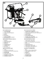
Container Contents
• Corrugated
Tube
Assembly
• Bag
containers
• Ba
ffl
es
• Collector
mount
• Cover
Assembly
• Bags of Hardware
• Blower
Assembly
• Drive
Pulley
• Belt
Shield
• Weight Mounting Bracket
• Weights
• Belt
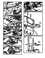
INSTALLING BLOW OUT BAFFLES
NOTE: The collection system includes optional deck ba
ffl
ing
designed to help prevent blow out when collecting in extremely
dry cutting conditions. If cutting conditions are not extremely
dry, ba
ffl
ing may not be required.
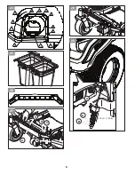
(Fig. 2)
NOTE: Leave all hardware loose until instructed to tighten.
1. Remove the hardware from deck's center ba
ffl
e.
2. Place the left-hand ba
ffl
e from the kit between the deck
skirt (A) and the front edge of deck.
3. Secure the left-hand ba
ffl
e (B) and the center ba
ffl
e (C) to
the deck skirt with four 1/4-20 x 1" carriage bolts and nuts
supplied with the kit, using a 7/16" wrench.
4. With a 1/2" wrench, install the right-hand ba
ffl
e (D) on
blade side of deck skirt and secure with two 5/16-18 x 1"
carriage bolts and nuts from the kit.
5. Tighten all hardware.
(See Operator Manual if necessary)
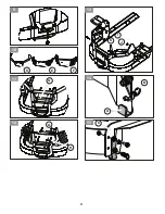
1. (152 cm (60 in) Commercial Decks Only) Remove the four
bolts securing the right-hand pulley cover bracket (A) to
the deck using a 1/2" wrench. Replace the bracket with the
new bracket from the kit, adding the three U-nuts to the
bracket sides and torque bracket bolts to 20 - 27 Nm (15-
20 ft-lbs.).
1. (137cm (54in) Commercial Decks Only) Add the U-nuts to
the front hole of the pulley cover bracket.
(Fig. 4 & 5)
2. Remove the nut (B) securing pulley to the right-hand deck
spindle using a 1 1/8" socket.
(Fig. 5)
3. Install drive pulley (C) included in collection system drive
kit on to the deck spindle.
(Fig. 6)
4. Reinstall the nut on the spindle using a 1 1/8” socket and
torque to 190 - 203 Nm (140-150 ft-lbs.).
5. Reinstall the deck belt.
NOTE: Use LARGER (approximately 11.4 cm (4 1/2") pulley for
152 cm (60 in) deck.
Use SMALLER (approximately 10.8 cm (4 1/4") pulley for 137
cm (54 in) deck.
Содержание Z400 COLLECTION SYSTEM
Страница 3: ...3 3 2 C B A D A 4 C 6 A 7 B C A 8 B 5 137 cm 54 in B 5 152 cm 60 in ...
Страница 4: ...4 D E F 10 G 11 G H 12 I J K 13 A B 14 C 15 9 ...
Страница 5: ...5 16 17 18 D 19 A B 20 C 21 A B 22 C 23 ...
Страница 6: ...6 A B C 29 3 18 cm 1 25 in 25 Z400 26 A B E D C 27 F 28 10 11 12 1 2 3 4 5 6 7 8 9 24 ...
Страница 55: ...55 ...
Страница 56: ...Printed in U S A 12 06 19 CL ...


