11
ASSEMBLY
WARNING!
Use extreme caution when towing. Never
allow children or others in or on the towed equipment.
Make wide turns to avoid jack-kni
fi
ng. Travel slowly and
allow extra distance to stop.
Do not tow on sloped ground. The weight of the towed
equipment may cause loss of traction and loss of control.
Follow the manufacturer's recommendation for weight limits
for towed equipment. Do not tow near ditches, canals, and
other hazards.
INSTALLING HITCH MOUNT
1. Using 3/8" wrench, remove guarding if present on the back
of the unit. Remove the two 5/16"-18 x 4” hex head bolts
and hardware using and 1/2” wrench and a ratchet with a
1/2” socket with 6” extension from the rear engine guard.
NOTE: Use caution to prevent skid plate from falling when
removing hardware from engine guard that is also used to hold
skid plate in place.
2. Using supplied 5/16"-18 x 4.5” hex head bolts and
hardware install hitch plate bracket (A) and hardware
loose before sliding skid plate between the hitch plate and
the face of the
fl
ange nuts.
(Fig. 7)
3. Tighten all hardware and reinstall guarding if removed.
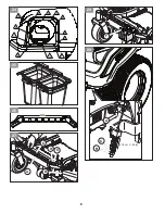
INSTALLING BAGGER MOUNT
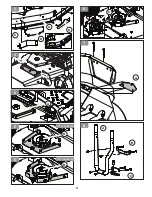
1. Find the mount tube (A), lower mount hitch (C) and upper
mount (B) from the kit. Place the 1/2"-13 x 1” hex head
fl
ange bolt through the lower mount hitch bracket (C).
(Fig. 8)
2. Attach the upper and lower mounts to the mount tube with
four 5/16"-16 x 2" carriage bolts and nuts with 1/2" wrench.
Be sure the elbowed arm of the tube is on the right side
with the mount hitches installed to the front of the unit.
(Fig. 9)
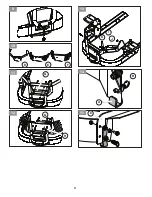
3. Place the bagger tube assembly on the hitch plate
attached to the unit and loosely install the 1/2” Nut to
the 1/2"-13 x 1" hex bolt that is positioned through the
lower hitch mount bracket (C) with a 3/4” wrench and 3/4”
socket.
(Fig. 10)
Models with Rear Guard (F)
4. It may be necessary to drill holes into the rear guard to
accept the hardware for the support bracket and spacer
plate. Using the lower three holes of the Upper Mount
Bracket (B ) as a template with the bagger mount tube
level, drill three 5/16" holes in the rear guard if holes are
not present, then proceed with the Models with Rear
Guard (D) directions below.
Models with Rear Guard (D)
4. Attach the tube assembly to the machine at the upper
mount (B) and spacer plate (G) between the rear guard
and upper mount bracket (B) with three 5/16" -18 x 1 1/4"
hex head
fl
ange bolts.
(Fig. 11)
Models with Rear Guard (E)
4. Attach the tube assembly to the machine at the upper
mount (B) and three spacers tubes (H) between the Rear
Guard with spacer plate (G) on the inside of the Rear
Guard with three 5/16" -18 x 1 1/2" hex head
fl
ange bolts
and nuts.
(Fig. 12)
Installing Bagger Straps
5. Install the mount straps (I/J), bends to the inside, on the
outside of the mount tube using 5/16"-18 x 2" carriage
bolts and nuts using a 1/2 socket.
6. Attach the front end of the mount straps to the fuel tank
brackets with 5/16"-18 x 1" carriage bolts and nuts.
(Fig. 13)
7. To prevent contact of the of the support straps with the
EFM (Electronic Fuel Management) box on the engine
or other critical components, place the foam strip (K)
on the inside of the strap after cleaning surface of
grease or debris, to prevent contact with least clearance
critical component. (Illustration location is approximate.
May be needed on right or left depending on engine
manufacturer.)
8. Tighten all hardware.
MOUNTING BLOWER ASSEMBLY
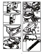
1. Locate and remove the lower rear latch assembly (A)
attached to the mounting bracket using a 9/16" wrench
and socket from the blower assembly. Pull the spring pin
(B) to release the assembly from the blower.
(Fig. 14)
2. The assembly will be reattached to the deck discharge
chute
fl
ange (C) at the rear of the deck. Attach the latch to
the outside of the deck
fl
ange using the top hole. Secure
the spring pin the in the bottom hole.
(Fig. 15)
NOTE: Older model decks may need to have the top hole
drilled into the deck.
3. Secure the latch to the deck with the spring pin and adjust
latch vertically on the
fl
ange. Mark the location of the
second hole and rotate the bracket out of the way. Drill a
7/16" hole at the mark.
(Fig. 16)
4. Move the latch assembly into place and attach the latch at
the top hole with the bolt, spacer and nut.
(Fig. 17)
NOTE: The latch assembly can remain on the deck when the
blower collection system is not used.
5. Slide the latch pins out and rotate up toward the upper
housing.
(Fig. 18)
6. Set the blower (D) on the deck with the mount slots over
the discharge chute mounting tabs.
7. Rotate the latch pin back down, assuring it passes through
the deck’s front discharge chute mounting tab.
Содержание Z400 COLLECTION SYSTEM
Страница 3: ...3 3 2 C B A D A 4 C 6 A 7 B C A 8 B 5 137 cm 54 in B 5 152 cm 60 in ...
Страница 4: ...4 D E F 10 G 11 G H 12 I J K 13 A B 14 C 15 9 ...
Страница 5: ...5 16 17 18 D 19 A B 20 C 21 A B 22 C 23 ...
Страница 6: ...6 A B C 29 3 18 cm 1 25 in 25 Z400 26 A B E D C 27 F 28 10 11 12 1 2 3 4 5 6 7 8 9 24 ...
Страница 55: ...55 ...
Страница 56: ...Printed in U S A 12 06 19 CL ...


