


1 1
S E T T IN G S A N D A D J U S T M E N T S
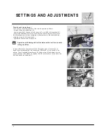
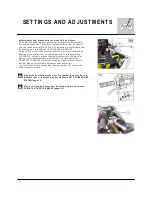
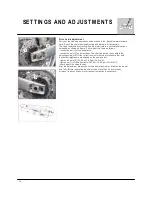
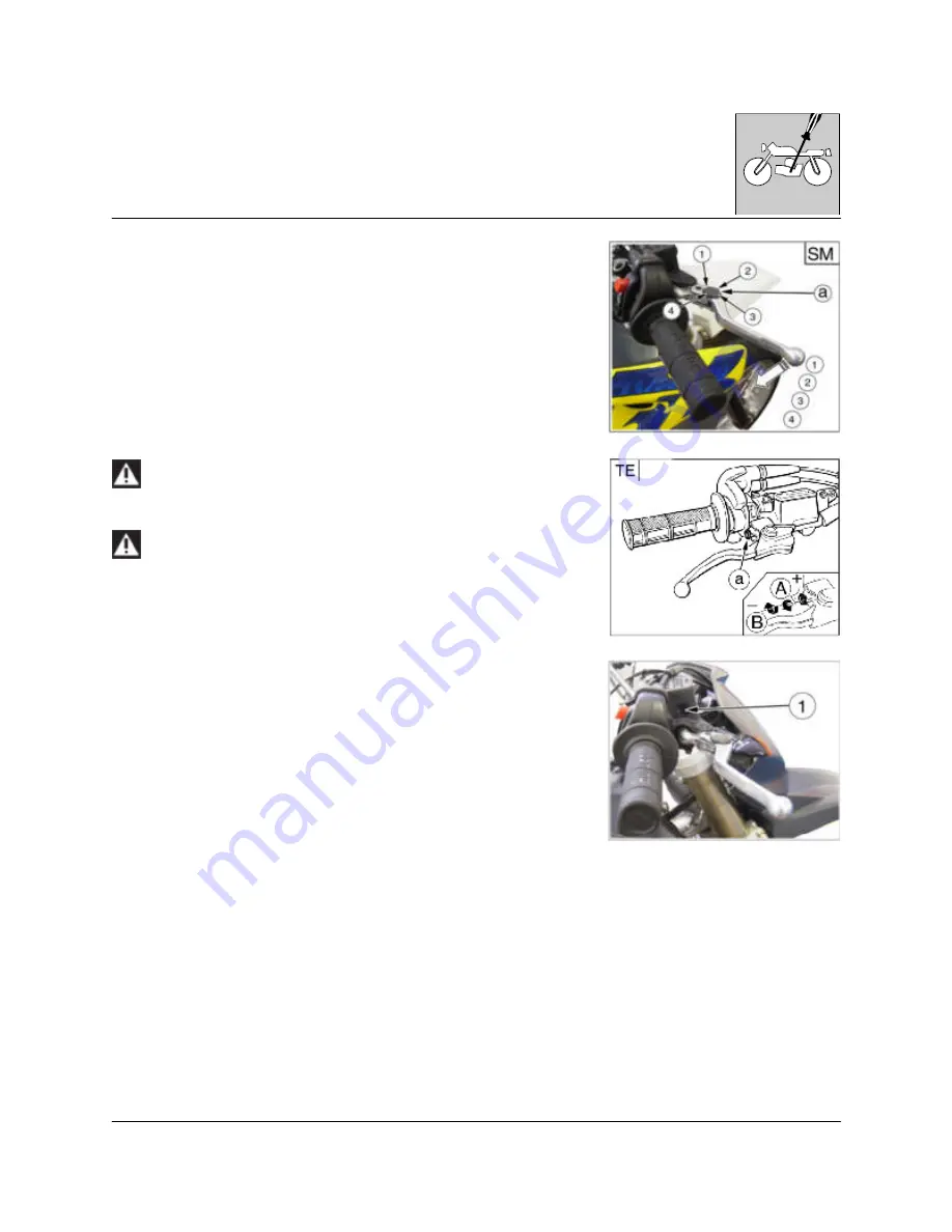
A d ju s tm e n t o f fro n t b ra k e c o n tro l le ve r a n d flu id le ve l c h e c k
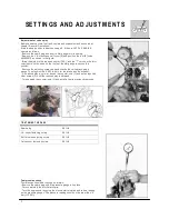
O n th e S M 6 1 0 m o d e l th e le ve r p o sitio n ca n b e a d ju ste d (4 a d ju stm e n ts)
fo r a n y d rive r h a n d size . T o d e cre a se th e le ve r d ista n ce fro m th e h a n d le
g rip , tu rn th e a d ju ste r (a ) C L O C K W IS E . T o in cre a se th e le ve r d ista n ce fro m
th e h a n d le g rip , tu rn th e a d ju ste r (1 ) C O U N T E R C L O C K W IS E .
O n th e T E 6 1 0 m o d e l th e a d ju ste r (a ), lo ca te d o n th e co n tro l le ve r, a llo w s
a d ju stin g o f th e p o sitio n fro m w h ich b ra kin g sta rts. T u rn th e a d ju ste r (a )
C L O C K W IS E in o rd e r to p o sitio n th e m a ste r c ylin d e r in su ch a w a y th a t
b ra kin g o ccu rs im m e d ia te ly u p o n le ve r a ctio n . T u rn th e a d ju ste r (a )
C O U N T E R C L O C K W IS E in o rd e r to p o sitio n th e m a ste r c ylin d e r in su ch a
w a y th a t b ra kin g o ccu rs slig h tly a fte rw a rd s u p o n le ve r a ctio n .
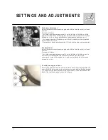
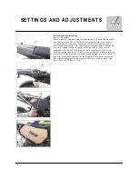
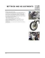
T h e fro n t flu id m u st n o t b e lo w e r th a n th e m in im u m le ve l (1 ) se e fro m th e
p u m p in sp e ctio n w in d o w .
If th e b ra k e le ve r fe e ls m u s h y w h e n it is a p p lie d , th e re m a y b e a ir in
th e b ra k e lin e s o r th e b ra k e m a y b e d e fe c tive : C H E C K T H E B R A K IN G
S Y S T E M (p a g e L .6 ).
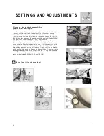
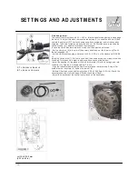
If th e le ve r fre e p la y is e x c e s s ive , th e b ra k e a c tio n c a n d e c re a s e :
C H E C K T H E P A D S T H IC K N E S S (p a g e L .5 ).
Содержание SM 610 2006
Страница 1: ...1 W orkshop Manual SM 610 TE 610 2006 Part N 8000 A4640 04 2005 ...
Страница 4: ...4 W here not otherwise specified data and instructions refer to all m odels SM 610 TE 610 ...
Страница 6: ...6 ...
Страница 7: ...1 GENERAL Section ...
Страница 15: ...1 Section MAINTENANCE ...
Страница 19: ...1 TROUBLESHOOTING Section ...
Страница 25: ...1 SETTINGS AND ADJUSTMENTS Section ...
Страница 41: ...1 GENERAL OPERATIONS Section ...
Страница 53: ...1 ENGINE DISASSEMBLY Section ...
Страница 74: ...22 ...
Страница 75: ...1 ENGINE OVERHAULING Section ...
Страница 100: ...26 ...
Страница 101: ...1 ENGINE REASSEMBLY Section ...
Страница 106: ...6 ENGINE REASSEMBLY ...
Страница 110: ...10 ENGINE REASSEMBLY A 28m m 1 1 in M AIN SHAFT B 25m m 0 98 in AUXILIARY SHAFT ...
Страница 129: ...1 FRONT SUSPENSION Section ...
Страница 144: ...16 ...
Страница 145: ...1 REAR SUSPENSION Section ...
Страница 153: ...9 REAR SUSPENSION ...
Страница 158: ...14 REAR SUSPENSION L 234 5 237 5 m m 9 23 9 35 in ...
Страница 163: ...1 BRAKES Section ...
Страница 171: ...9 BRAKES Periodically check the connecting hoses A and B if the hoses are worn or cracked their replacem ent is advised ...
Страница 172: ...10 ...
Страница 173: ...1 ELECTRIC SYSTEM Section ...
Страница 176: ...4 ELECTRIC SYSTEM ...
Страница 179: ...7 ELECTRIC SYSTEM ...
Страница 197: ...25 ELECTRIC SYSTEM Fig 1 Fig 2 Fig 3 Fig 4 Fig 5 Fig 1 Fig 7 Fig 8 Fig 9 Fig 10 Fig 6 Fig 12 Fig 11 ...
Страница 202: ...30 ELECTRIC SYSTEM TE SM L H COM M UTATOR ...
Страница 205: ...1 ENGINE COOLING SYSTEM Section ...
Страница 208: ...4 ...
Страница 209: ...1 LUBRICATION CIRCUIT Section ...
Страница 211: ...1 SPECIFIC TOOLS Section ...
Страница 219: ...1 FRAME AND W HEELS Section ...
Страница 229: ...1 NOTES FOR USA CDN AUS MODELS Section ...