


6
E L E C T R IC S Y S T E M
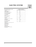
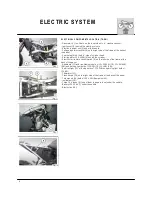
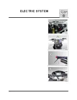
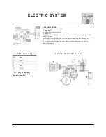
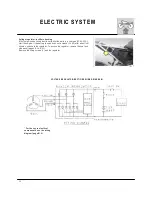
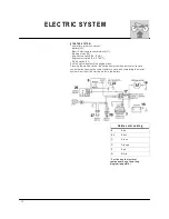
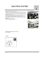
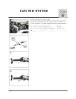
E L E C T R IC A L C O M P O N E N T S L O C A T IO N (T E -S M )
- G e n e ra to r (1 ), in o il b a th , o n th e in n e r sid e o f L .H . cra n kca se co ve r;
- Ig n itio n co il (2 ) b e h in d th e ste e rin g co lu m n ;
- E le ctro n ic p o w e r u n it (3 ) u n d e r th e sa d d le ;
- V o lta g e re g u la to r-re ctifie r (4 ) o n th e rig h t sid e o f th e fra m e a t th e b a ck o f
th e p a n e l;
- S p a rk p lu g (5 ) o n th e R .H . sid e o f c ylin d e r h e a d ;
- S ta rtin g m o to r 1 2 V -4 5 0 W (6 ) b e h in d th e c ylin d e r;
- E le ctric sta rt re m o te co n tro l s w itch (8 ) o n th e le ft sid e o f th e fra m e a t th e
b a ck o f th e p a n e l.
- H e a d la m p (1 1 ) w ith tw o fila m e n ts b u lb o f 1 2 v-3 5 /3 5 W (T E ), 1 2 v 5 5 /6 0 W
(S M ) a n d p a rkin g lig h t b u lb o f 1 2 V -3 W (T E ), 1 2 v-5 W (S M );
- R e a r ta il-lig h t (1 2 ) w ith sto p b u lb s o f 1 2 V -2 1 W a n d p a rkin g lig h t b u lb o f
1 2 V -5 W ;
- T h e rm isto r (1 3 );
- F la sh d e vice (1 6 ) o n th e rig h t sid e o f th e fra m e a t th e b a ck o f th e p a n e l;
- T u rn sig n a ls (1 4 ) b u lb o f 1 2 V -1 0 W (E q u ip m e n t kit);
- In stru m e n t (1 5 );
- T h re e 1 5 A fu s e s (9 ) (o n e o f th e m is a sp a re fu se ) u n d e r th e sa d d le ;
- B a tte ry 1 2 V -1 2 A h (7 ) u n d e r th e sa d d le
- E le ctric fa n (1 0 ).
Содержание SM 610 2006
Страница 1: ...1 W orkshop Manual SM 610 TE 610 2006 Part N 8000 A4640 04 2005 ...
Страница 4: ...4 W here not otherwise specified data and instructions refer to all m odels SM 610 TE 610 ...
Страница 6: ...6 ...
Страница 7: ...1 GENERAL Section ...
Страница 15: ...1 Section MAINTENANCE ...
Страница 19: ...1 TROUBLESHOOTING Section ...
Страница 25: ...1 SETTINGS AND ADJUSTMENTS Section ...
Страница 41: ...1 GENERAL OPERATIONS Section ...
Страница 53: ...1 ENGINE DISASSEMBLY Section ...
Страница 74: ...22 ...
Страница 75: ...1 ENGINE OVERHAULING Section ...
Страница 100: ...26 ...
Страница 101: ...1 ENGINE REASSEMBLY Section ...
Страница 106: ...6 ENGINE REASSEMBLY ...
Страница 110: ...10 ENGINE REASSEMBLY A 28m m 1 1 in M AIN SHAFT B 25m m 0 98 in AUXILIARY SHAFT ...
Страница 129: ...1 FRONT SUSPENSION Section ...
Страница 144: ...16 ...
Страница 145: ...1 REAR SUSPENSION Section ...
Страница 153: ...9 REAR SUSPENSION ...
Страница 158: ...14 REAR SUSPENSION L 234 5 237 5 m m 9 23 9 35 in ...
Страница 163: ...1 BRAKES Section ...
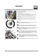
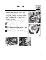
Страница 171: ...9 BRAKES Periodically check the connecting hoses A and B if the hoses are worn or cracked their replacem ent is advised ...
Страница 172: ...10 ...
Страница 173: ...1 ELECTRIC SYSTEM Section ...
Страница 176: ...4 ELECTRIC SYSTEM ...
Страница 179: ...7 ELECTRIC SYSTEM ...
Страница 197: ...25 ELECTRIC SYSTEM Fig 1 Fig 2 Fig 3 Fig 4 Fig 5 Fig 1 Fig 7 Fig 8 Fig 9 Fig 10 Fig 6 Fig 12 Fig 11 ...
Страница 202: ...30 ELECTRIC SYSTEM TE SM L H COM M UTATOR ...
Страница 205: ...1 ENGINE COOLING SYSTEM Section ...
Страница 208: ...4 ...
Страница 209: ...1 LUBRICATION CIRCUIT Section ...
Страница 211: ...1 SPECIFIC TOOLS Section ...
Страница 219: ...1 FRAME AND W HEELS Section ...
Страница 229: ...1 NOTES FOR USA CDN AUS MODELS Section ...