background image

HYDRAULIC AND PARK BRAKE SYSTEMS

Park Brake System

2005 HUV4420 Gasoline and HUV4420-D Diesel Vehicle Maintenance and Service Manual

Page 5-29

5

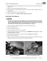
Lower Frame Pulley Installation

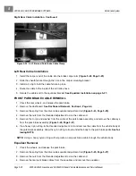
1. Position a new pulley on the lower frame mount, and secure the pulley with four bolts, washers, and lock-

nuts. Tighten the hardware to 4.5 ft-lb (6.0 N·m).

Park Brake Pulleys Installation

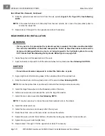
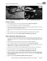
1. Position two new pulleys on the pulley mounting plate.

2. Secure each pulley assembly with four bolts, washers, and locknuts. Tighten the hardware to 4.5 ft-lb (6

N·m).

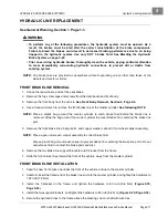
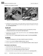
3. Position the pulley mounting plate and the park brake assembly on the front part of the vehicle frame.

4. Secure the pulley mounting plate and park brake assembly with three bolts and locknuts. Tighten the

hardware to 15 ft-lb (20 N·m).

5. Install the front park brake cable. 

See Front Park Brake Cable Installation on page 5-27.

6. Install the dashboard. 

See Dashboard Installation, Section 4, Page 4-4.

7. Install the front body. 

See Front Body Installation, Section 4, Page 4-5.

Содержание HUV4420

Страница 1: ... 5 5 2 4 56 56 3 3 6 3 4 3 26 5 ...

Страница 2: ......

Страница 3: ...irs to the vehicle may render the vehicle unsafe For this reason Husqvarna advises that all repairs and or service be performed by an authorized Husqvarna distributor dealer representative or by a Husqvarna fac tory trained technician It is the policy of Husqvarna to assist its distributors and dealers in continually updating their service knowl edge and facilities so they can provide prompt and e...

Страница 4: ... future edi tions of this manual Damage to a vehicle or component thereof not resulting from a defect or that occurs due to unrea sonable or unintended use overloading abuse or neglect including failure to provide reasonable or necessary maintenance as instructed in the vehicle owner s manual accident or alteration including increasing vehicle speed beyond factory specifications or modifications t...

Страница 5: ...he Stored Vehicle to Service 3 3 SECTION 4 BODY AND TRIM Cleaning the Vehicle 4 1 Seat Cleaning 4 1 Front Body Repair 4 2 Abrasions and Haze 4 2 Light Scratches 4 2 Large Scratches and Abrasions 4 2 Front Body Components 4 2 Instrument Panel Removal 4 2 Instrument Panel Installation 4 4 Dashboard Removal 4 4 Dashboard Installation 4 4 Front Body Removal 4 5 Front Body Installation 4 5 Front Fender...

Страница 6: ...ed Lift Motor Removal 4 9 Bed Lift Motor Installation 4 9 Cargo Bed Removal 4 10 Cargo Bed Installation 4 10 Rear Fender 4 10 Rear Fender Removal 4 10 Rear Fender Installation 4 10 Floor Mat 4 11 Floor Mat Removal 4 11 Floor Mat Installation 4 11 SECTION 5 HYDRAULIC AND PARK BRAKE SYSTEMS Brake System Inspection 5 1 Brake System Troubleshooting 5 3 Brake Pads and Caliper 5 5 Front Brake Pad and Ca...

Страница 7: ... Bleeding the Hydraulic Brake System 5 22 Purging the Hydraulic System 5 23 Park Brake System 5 23 Park Brake Adjustment 5 23 Park Brake Cable Adjustment 5 24 Park Brake Wheel Cables 5 24 Front Park Brake Cable Removal 5 26 Front Park Brake Cable Installation 5 27 Park Brake Pedal 5 28 Park Brake Pulleys 5 28 SECTION 6 ACCELERATOR AND BRAKE PEDAL ASSEMBLIES Accelerator Pedal 6 1 Accelerator Pedal ...

Страница 8: ...ly 7 7 Front Suspension 7 10 Wheel Alignment 7 10 Front Suspension Components 7 13 Steering Upright Removal 7 13 Upper A Arm Removal 7 14 Upper A Arm Installation 7 15 Lower A Arm Removal 7 16 Lower A Arm Installation 7 17 Front Coil Over Shock Absorber Removal 7 17 Front Coil Over Shock Absorber Installation 7 18 Steering Upright Installation 7 19 SECTION 8 WHEELS AND TIRES General Information 8 ...

Страница 9: ...Rear Differential 10 11 Engine Coolant Diesel Vehicles 10 12 Engine Coolant Level Check 10 12 Fueling Instructions 10 12 Draining Water from Fuel Filter 10 13 Battery 10 14 SECTION 11A TROUBLESHOOTING AND ELECTRICAL SYSTEM GASOLINE VEHI CLES Troubleshooting Guide 11a 1 Wiring Diagram 11a 6 Test Procedures 11a 8 Index of Test Procedures 11a 8 SECTION 11B TROUBLESHOOTING AND ELECTRICAL SYSTEM DIESEL...

Страница 10: ...cuit Breaker 12a 15 Battery 12a 15 General Information 12a 16 SECTION 12B ELECTRICAL COMPONENTS DIESEL VEHICLES Starter and Starter Solenoid 12b 1 Relays 12b 1 Neutral Switch 12b 2 Fuel Solenoid 12b 2 50 Amp Circuit Breaker 12b 3 Instrument Panel 12b 4 Key Switch 12b 5 Fuse 12b 6 Reverse Warning Buzzer 12b 7 Low Oil Warning Light 12b 9 Fuel Gauge Hour Meter 12b 10 Electric Fuel Pump 12b 11 Fuel Le...

Страница 11: ...13a 13 Fuel Lines 13a 15 Fuel Shut Off Valve 13a 16 Oil Filter Hoses 13a 17 Oil Viscosity 13a 17 Engine Control Linkages 13a 18 Accelerator Cable 13a 18 Governor Guard 13a 20 Governor Cable 13a 21 Accelerator Cable Retention Clip Adjustment 13a 22 Ground Speed Transmission Governor Arm Adjustment 13a 23 Engine Governor Arm 13a 25 Engine RPM Adjustment 13a 25 Choke and Air Intake System 13a 26 Air ...

Страница 12: ...lation 13b 7 Intermediate Pipe Installation 13b 7 Muffler Installation 13b 8 Fuel System 13b 9 Fuel Line Hose Replacement 13b 9 Fuel Filter Replacement 13b 9 Draining Water from the Secondary Fuel Filter 13b 9 Electric Fuel Pump 13b 12 Fuel Level Sending Unit 13b 15 Fuel Tank 13b 18 Fuel Lines 13b 21 Engine Control Linkages 13b 21 Accelerator Cable 13b 21 Engine RPM Adjustment 13b 23 Air Intake Sy...

Страница 13: ...eshaft 14 6 Front Driveshaft Removal 14 6 Front Driveshaft Installation 14 7 Rear Receiver Hitch 14 7 Rear Receiver Hitch Removal 14 7 Rear Receiver Hitch Installation 14 7 Rear Axle 14 8 Rear Axle Removal 14 8 Rear Axle Installation 14 10 Rear Driveshaft 14 11 Rear Driveshaft Removal 14 11 Rear Driveshaft Installation 14 12 Transmission 14 12 Transmission Removal 14 12 Transmission Installation 1...

Страница 14: ...16 1 Transmission Removal 16 2 Transmission Disassembly 16 2 Input Shaft Disassembly 16 8 Input Shaft Assembly 16 8 Intermediate Shaft Disassembly 16 8 Output Shaft Disassembly 16 12 Shifter Shaft Removal 16 13 Shifter Shaft Installation 16 14 Case Inspection 16 14 Shaft Seal Removal 16 15 Shaft Seal Installation 16 15 Output Shaft Assembly 16 15 Intermediate Shaft Assembly 16 18 Intermediate and ...

Страница 15: ...sembly 17 8 Front Differential Assembly 17 14 Front Differential Installation 17 18 Axle Half Shaft Installation 17 18 SECTION 18 REAR DIFFERENTIAL MODELS 420366 AND 420851 General Information 18 1 Rear Differential Disassembly 18 2 Pinion Gear Removal 18 4 Ring Gear Removal 18 6 Clutch Carrier Assembly 18 7 Ring Gear Installation 18 8 Pinion Gear Installation 18 9 Rear Differential Assembly 18 9 ...

Страница 16: ...Page xiv 2005 HUV4420 Gasoline and HUV4420 D Diesel Vehicle Maintenance and Service Manual ...

Страница 17: ...damage GENERAL WARNING The following safety statements must be heeded whenever the vehicle is being operated repaired or ser viced Service technicians should become familiar with these safety statements which can be found through out this manual Also other specific safety statements appear throughout this manual and on the vehicle ý DANGER Battery Explosive gases Do not smoke Keep sparks and flame...

Страница 18: ...hen working on or near batteries Do not wear loose clothing or jewelry such as rings watches chains etc when servicing the vehicle Moving parts Do not attempt to service the vehicle while it is running Hot Do not attempt to service hot engine or exhaust system Failure to heed this warning could result in severe burns Use insulated tools when working near batteries or electrical connections Use ext...

Страница 19: ... is equipped with a prop rod ensure that it is securely engaged while bed is raised Do not close bed until all persons are clear of cargo bed area Keep hands clear of all crush areas Do not drop cargo bed lower gently and keep entire body clear Failure to heed this warning could result in severe personal injury or death Improper use of the vehicle or failure to properly maintain it could result in...

Страница 20: ...1 ...

Страница 21: ...e speed dry type STEERING SUSPENSION BRAKES Steering Self adjusting rack and pinion Ackerman Suspension Front Independent A arms with coil over shock absorbers Rear Semi independent suspension with multi leaf springs and dual hydraulic shock absorbers Brakes Hydraulic brake system brake pads and discs on each wheel with separate foot operated park brake BODY CHASSIS Frame Chassis Twin I Beam welde...

Страница 22: ... CAPACITIES Engine crankcase with filter SAE 10W 30 API classification SJ 1 8 qt 1 7 L Engine crankcase with filter SAE 10W 30 API classification CF 3 qt 2 8 L Front differential Mobil 424 Exxon Hydraul 560 or Esso Hydraul 56 lubrication 5 oz 150 mL Rear differential Mobil 424 Exxon Hydraul 560 or Esso Hydraul 56 lubricant 20 oz 600 mL Transmission Mobil 424 Exxon Hydraul 560 or Esso Hydraul 56 lu...

Страница 23: ...ing on a Trailer Engine Oil and Filter Change Accessory Equipment Subsequent Owner Registration Warranties MODEL IDENTIFICATION The serial number of each vehicle is printed on a bar code decal mounted on the frame directly above the accelerator pedal Example DH0501 123456 Figure 3 1 Page 3 1 There is also a second serial number decal mounted on the rear body frame behind the fuel tank The fuel tan...

Страница 24: ... EXTENDED STORAGE 1 Unload the vehicle so that the tires are supporting only the weight of the vehicle 2 Store the vehicle in a cool dry place This will minimize battery self discharge If the battery appears to be weak have it charged by a trained technician Use an automotive type 12 volt battery charger rated at 10 amps or less Check electrolyte level after charging and add distilled water if nec...

Страница 25: ...s and Tires 11 Perform semiannual periodic lubrication See Periodic Lubrication Schedule on page 10 4 12 Thoroughly clean the front body rear body seats cargo bed engine compartment and underside of vehicle 13 Do not engage the park brake Chock the wheels to prevent the vehicle from rolling RETURNING THE STORED VEHICLE TO SERVICE 1 Make sure the key switch is in the OFF position and the Forward Re...

Страница 26: ...tion for storage the engine may smoke excessively for a short time when it is run for the first time after storage 6 Perform the Pre Operation and Daily Safety Checklist See the Pre Operation and Daily Safety Checklist in the vehicle owner s manual Figure 3 4 Fuel Shut Off Valve Open Position Figure 3 5 Fuel Shut Off Valve Closed Position Figure 3 6 Fuel Shut Off Valve Partially Closed Position FU...

Страница 27: ...s with a sponge or soft cloth Repair kits and cleaning polishing products are also available at most hardware stores where ABS DR acrylic products hot tubs and shower tub units are sold To remove oxidation or discoloration from aluminum use a commercially available aluminum cleaner paste and fine grade No 00 steel wool Battery acid fertilizers tars asphalt creosote paint or chewing gum should be r...

Страница 28: ...uivalent thickness of an average business card can be removed by light sanding Start with wet silicone carbide abrasive paper 320 grit or finer Use progressively finer grits i e 400 600 800 to reduce sanding marks Use Ajax cleanser or equivalent for final smoothing A Micro Mesh acrylic polishing kit with abrasive papers from 1800 to 8000 grit will provide the best final finish Restore gloss with s...

Страница 29: ... rubber grommet and cable from the engine plate 3 4 7 Remove the cable from the two grommets under the frame See following NOTE NOTE Removing the rubber grommets from the cable will allow the cable to pass smoothly past wiring and structural components Tie a nylon cord to the end of the cable before removal Route the cord from the engine under the frame and up to the instrument panel to be used du...

Страница 30: ...void unintentionally starting in General Warning Section 1 Page 1 2 3 Remove the steering wheel See Steering Wheel Removal Section 7 Page 7 1 4 Remove the instrument panel See Instrument Panel Removal on page 4 2 5 Remove the five plastic caps from the point where dashboard and front body meet 6 Remove the five Torx head screws with special plastic washers from the top of the dashboard 7 Remove th...

Страница 31: ...ws that have special plastic washers and tighten the hardware to 45 in lb 5 1 N m 4 Install five plastic caps 5 Secure the front body with six Tuflok fasteners FRONT FENDER REMOVAL 1 Remove the front body See Front Body Removal on page 4 5 2 Pull back the floor mat and remove the two Torx head screws securing the front fender to the floor 3 Remove the screws from the fender support and remove the ...

Страница 32: ... that secure the two vertical rear bars 2 and remove the rear bars 2 from the top structure 1 ROPS INSTALLATION NOTE Roll over Protective Structure ROPS installation will be easier with a helper 1 Install two rear vertical bars 2 on the top structure 1 and secure the bars with two bolts 4 two wash ers 6 and two locknuts 5 Tighten the hardware to 33 ft lb 45 N m 2 Install the two front vertical bar...

Страница 33: ...e hardware to 96 in lb 10 8 N m 1 5 Install the seat See following WARNING ý WARNING Ensure that the seat hinges and latch are securely engaged before operating vehicle 2 Driver Seat 2 1 Sit in seat grasp seat adjustment handle under seat bottom and slide seat to desired position See preceding WARNING SEAT INSTALLATION 1 Align the hinges on the underside of the seat front edge with the hinge slots...

Страница 34: ...ts may interfere with the buckle locking mechanism If the safety belt does not function normally contact your Husqvarna dealer distributor or trained technician immediately Do not occupy the seat until the safety belt is repaired SAFETY BELT REMOVAL 1 Remove the bolt from the base of the coiled safety belt assembly outside location Figure 4 5 Page 4 8 2 Remove the coiled safety belt assembly 3 Rem...

Страница 35: ... bed frame 5 Remove the lock nut bolt sleeve spacers and washers from the base of the bed lift motor and vehicle frame and remove the bed lift motor BED LIFT MOTOR INSTALLATION NOTE If replacing the actuator adjust the length of dimension between the base rod hole and the rod end hole using the prior actuator as a guide The rod end of the actuator can be turned clockwise to shorten and countercloc...

Страница 36: ...al and installation will be easier with the aid of an assistant 1 With the help from an additional person or an overhead lift hoist place the bed onto the vehicle frame and align the bed hinge brackets with the frame brackets 2 Start the bolts into both hinges with the bolt heads to the outside Use an alignment tool if necessary 3 Use a small hammer and lightly tap the bolts through the hinges 4 I...

Страница 37: ...ge 4 11 4 FLOOR MAT See General Warning Section 1 Page 1 1 FLOOR MAT REMOVAL 1 Lift the back edge of the floor mat and slide the front edge down and away from the aluminum mat shield FLOOR MAT INSTALLATION 1 Slide the mat up and under the aluminum mat shield and tuck the rear edge down against the seat panel ...

Страница 38: ...4 ...

Страница 39: ...pedal from side to side to check for worn parts Excessive side movement indicates loose or worn pedal mounting parts If worn parts are found replace the worn parts then adjust the brake pedal See Brake Pedal Adjustment Section 6 Page 6 4 Apply heavy pressure to the pedal and check for sponginess and excessive pedal travel The pedal should be firm If the brake pedal feels spongy perform the brake b...

Страница 40: ...ge 5 17 Turn the steering wheel all the way from left to right and back again Contact between the brake hoses and any other components especially the wheels or half shafts will damage the brake hoses Check the back side of each brake caliper assembly for signs of brake fluid leakage If there is evi dence of leakage determine the cause and repair or replace as needed See Brake Pads and Caliper on p...

Страница 41: ...re should be at least 0 020 inches 0 5 mm of brake pad material at the thinnest point See follow ing WARNING ý WARNING Use only approved replacement brake pads designed for your vehicle Use only DOT 5 brake fluid Do not pump brake pedal without fluid in the reservoir or master cylinder BRAKE SYSTEM TROUBLESHOOTING The procedures used in making the checks provided in the following troubleshooting g...

Страница 42: ...d Replace master cylinder See Master Cylinder and Reservoir on page 5 20 Over aggressive braking Incorrect or distorted brake pads Replace the brake pads See Brake Pads and Caliper on page 5 5 Vehicle pulls to one side Incorrect or distorted brake pads Replace the brake pads See Brake Pads and Caliper on page 5 5 Grease or brake fluid on the brake pads Replace hub axle seal or caliper and replace ...

Страница 43: ...n brake pads Replace the brake pads See Brake Disc and Hub on page 5 10 Brake discs are cracked or scored Replace the brake discs See Brake Disc and Hub on page 5 10 All brakes drag Binding brake pedal Replace bushings and adjust Also replace any bent or damaged components See Section 6 Accelerator and Brake Pedal Assemblies Soft or swollen rubber parts caused by incorrect or contaminated brake fl...

Страница 44: ...nd Figure 5 2 Page 5 6 3 Remove the lug nuts and front wheel Front Brake Pad Removal 1 Remove the two socket head slide pin bolts securing the top and bottom of the two brake pads Figure 5 3 Page 5 7 2 Remove the brake pads Front Brake Caliper Removal 1 Remove the banjo bolt and copper washers holding the brake line to the caliper body Figure 5 4 Page 5 7 See following NOTE NOTE Place a clean tray...

Страница 45: ... banjo bolt and new copper washers Tighten to 13 ft lb 18 N m See following CAUTION ý CAUTION The banjo bolts are metric Use only metric thread replacements 3 Bleed the brake line at the top bleed port on the caliper body Tighten the port fitting to 27 in lb 3 N m See following NOTE NOTE Front wheel calipers for this vehicle are equipped with two bleed ports These calipers can be used on either th...

Страница 46: ...raulic connections to prevent dirt or debris from entering system 1 Chock the front wheels release the park brake loosen the rear wheel lug nuts and lift the rear of the vehicle with a chain hoist or floor jack See WARNING Lift only one end in General Warning Section 1 Page 1 2 2 Place jack stands under the rear axle and lower onto stands 3 Remove lug nuts and rear wheel Rear Brake Pad Removal 1 R...

Страница 47: ...lt and new copper washers Tighten the hardware to 13 ft lb 18 N m See following NOTE and CAUTION NOTE Position the brake line so it is perpendicular to the caliper assembly and pointing directly toward the base bracket on the shock absorber CAUTION The banjo bolts are metric Use only metric thread replacements 3 Bleed the brake line at the bleed port on the caliper body See following NOTE NOTE Ind...

Страница 48: ... reinstallation of the brake components Failure to bleed the brakes could result in decreased braking performance due to air being trapped in the hydraulic system Use only DOT 5 brake fluid See Bleeding the Hydraulic Brake System on page 5 22 ý CAUTION Worn or damaged brake discs cannot be machined to refinish them Replace as necessary 1 Chock the rear wheels set the park brake loosen the front wh...

Страница 49: ... not to tear or puncture the rubber seal around the ball socket If damaged the ball joint with rubber boot must be replaced 9 Remove the wheel hub disc and bearing assembly from the splined spindle and CV joint half shaft 10 Remove the wheel hub and disc from the bearing and upright See following CAUTION and NOTE CAUTION The wheel disc and hub are one piece and the splined shaft of the hub is pres...

Страница 50: ...be damaged when the hub and disc are removed Replace the bearings during reas sembly 11 Remove the snap ring 9 from the bearing cavity 7 in the upright 5 Figure 5 12 Page 5 12 12 Press the bearing out of the upright 12 1 Position the upright 5 with the two ball joint arms down on one steel block 1 and the drag link arm down on a second steel block 1 Figure 5 13 Page 5 12 12 2 Shim the ball joint a...

Страница 51: ...g cavity above the bearing Figure 5 12 Page 5 12 15 Press the shaft on the disc and hub into the bearing Figure 5 15 Page 5 13 15 1 Position the disc and hub 6 onto a 2 x 2 inch or larger steel block as shown Figure 5 15 Page 5 13 See following CAUTION CAUTION Do not press against the lug bolts Press only against the center of the hub 15 2 Apply anti seize compound to the hub and disc shaft 15 3 P...

Страница 52: ... the CV joint spindle See following CAUTION CAUTION Do not allow anti seize compound to contact the brake disc or pads 4 Apply anti seize compound to the upper and lower ball joint stud studs 5 Secure the upright wheel and bearing assembly to the upper ball joint Use a new nylon lock nut and tighten the hardware to 18 ft lb 24 N m 6 Secure the upright wheel and bearing assembly to the lower ball j...

Страница 53: ...on of the brake components Failure to bleed the brakes could result in decreased braking performance due to air being trapped in the hydraulic system Use only DOT 5 brake fluid See Bleeding the Hydraulic Brake System on page 5 22 1 Chock the front wheels release the park brake and loosen the rear wheel lug nuts 2 Remove the rubber dust cap 3 Remove and discard the cotter pin 4 Loosen and discard t...

Страница 54: ...hreaded portion of the axle 2 Apply anti seize compound to both the axle and wheel hub splined area See following CAUTION CAUTION Do not allow anti seize compound to contact the brake disc or pads 3 Apply a light coat of lubrication grease to the outside surface of the splined hub 4 Slide the wheel hub onto the splined portion of the axle end See following NOTE NOTE Ensure the splined hub is posit...

Страница 55: ...ion 4 Page 4 5 4 Use a flare nut wrench to remove the front brake line at the master cylinder See following NOTE NOTE Place a plastic bag around the master cylinder to catch brake fluid before the brake line is removed Wrap the bag around the master cylinder to prevent debris from entering the brake line port 5 Remove the front brake lines banjo bolts and copper washers at each front wheel caliper...

Страница 56: ...er and bleed the hydraulic system See Bleeding the Hydraulic Brake System on page 5 22 8 Inspect the brake system See Brake System Inspection on page 5 1 See following WARNING ý WARNING Use the top bleeding port on each caliper to bleed that respective front wheel 9 Install the front body See Front Body Installation Section 4 Page 4 5 10 Secure the dashboard and front body to the frame See Dashboa...

Страница 57: ...e until it clears the rear of the vehicle During replacement tie the flare nut end of the new brake line to the nylon string and use it to pull the new brake line into position and to the master cylinder REAR BRAKE LINE INSTALLATION 1 Feed a new brake line from the rear of the vehicle and position it in line with the frame clamps and up to the master cylinder See following NOTE NOTE If a heavy nyl...

Страница 58: ...following NOTE NOTE Provide a clean container for the brake fluid to drain into After both hose ends are in a container remove the reservoir cap to allow fluid to drain freely from reservoir container 6 Remove the hoses at the reservoir NOTE If hoses are cracked or show signs of aged deterioration replace them with approved hoses designed to handle brake fluid specified for this vehicle 7 Remove t...

Страница 59: ...dy See Front Body Removal Section 4 Page 4 5 4 Remove the hoses from the master cylinder See following NOTE NOTE Use a clean container to collect the brake fluid After both hose ends have been placed in a con tainer remove the reservoir cap and allow fluid to drain freely from the reservoir container If hoses are cracked or show signs of deterioration replace them with approved hoses designed to h...

Страница 60: ...ic system must be free of air Air enters the hydraulic system whenever the system is opened and will result in a spongy brake pedal The master cylinder controls two separate hydraulic sub systems The front two wheels are connected to the front portion of the master cylinder and the rear wheels to the rear portion One or both sub systems may require bleeding depending on where the hydraulic system ...

Страница 61: ... entire hydraulic brake system of brake fluid To completely purge the hydraulic system perform the following procedure 1 Perform steps 2 through 6 5 of Bleeding the Hydraulic Brake System Section 5 Page 5 22 2 Draw 1 qt 0 9464 L of the brake fluid into the vacuum type brake bleeder tool 3 With the vacuum running tighten the two top bleeder valves 4 Allow the handle on the brake bleeder tool to ope...

Страница 62: ...5 Release the park brake pedal and push it again to eight clicks The vehicle should not be movable with one person pushing 6 Tighten the equalizer jam nut against the conical nut and tighten to 55 in lb 6 3 N m NOTE The park brake should not allow the vehicle to roll when pushed with the park brake pedal in the eighth click eight clicks from the top of the pedals travel 7 Inspect the brake system ...

Страница 63: ...Right Rear Cable Installation 1 Install the caliper end of the cable into the brake caliper arm Figure 5 22 Page 5 25 2 Slide the sheath ferrule through the hole in the caliper mounting bracket 3 Install a C clip to hold the cable ferrule in place 4 Route the cable up and across the air filter box and secure the cable bracket to the top bolt on the filter mounting bracket Figure 5 24 Page 5 26 5 R...

Страница 64: ... the driver side equalizer adjustment rod Figure 5 23 Page 5 25 4 Remove the nuts from the threaded adjustment rod on the cable end 5 Remove the C clip and washer from the cable at the park brake assembly and remove the cable eye from the park brake assembly Figure 5 26 Page 5 27 6 Tie a heavy nylon string to the threaded adjustment rod and remove the cable from the vehicle body at the park brake ...

Страница 65: ...nder the vehi cle body and toward the driver side rear park brake cable See Front Park Brake Cable Removal on page 5 26 2 Route the cable over each of the two front cable pulleys and under the lower pulley 3 Insert the threaded adjustment rod through the equalizer bracket Figure 5 25 Page 5 27 4 Install the conical nut with the cone oriented toward the equalizer and then install a jam nut onto the...

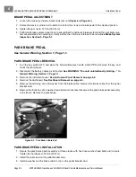
Страница 66: ...rake Pulley Removal 1 Chock the wheels and release the park brake 2 Remove the dashboard See Dashboard Removal Section 4 Page 4 4 3 Remove the front body See Front Body Removal Section 4 Page 4 5 4 Remove the spring from the driver side equalizer adjustment rod Figure 5 25 Page 5 27 5 Remove the nuts from the threaded adjustment rod on the cable end 6 Remove the cable end from the equalizer bracke...

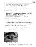
Страница 67: ... pulley mounting plate 2 Secure each pulley assembly with four bolts washers and locknuts Tighten the hardware to 4 5 ft lb 6 N m 3 Position the pulley mounting plate and the park brake assembly on the front part of the vehicle frame 4 Secure the pulley mounting plate and park brake assembly with three bolts and locknuts Tighten the hardware to 15 ft lb 20 N m 5 Install the front park brake cable ...

Страница 68: ...5 ...

Страница 69: ...tentionally starting in General Warning Section 1 Page 1 1 3 Remove the dashboard See Dashboard Removal on page 4 4 4 Disconnect the cable strain relief from the pedal bracket 5 Disconnect the Z shaped end 1 of the accelerator cable from the pedal Figure 6 1 Page 6 1 6 Remove the pedal assembly bolts and lock nuts that secure the pedal assembly to the frame 7 Slide out and twist the pedal to remov...

Страница 70: ...ew to 3 4 inches 19 mm as shown Figure 6 3 Page 6 2 3 Turn the key switch to start the engine See following DANGER ý DANGER The engine produces carbon monoxide which is an odorless deadly poison Do not operate the engine in an enclosed area without proper ventilation 4 Press the accelerator pedal and allow the engine to achieve full steady level RPM See following NOTE NOTE This process should only...

Страница 71: ...G To avoid unintentionally starting in General Warning Section 1 Page 1 1 3 Remove the dashboard See Dashboard Removal on page 4 4 4 Remove the rue pin and the clevis pin Separate the clevis from the brake pedal Figure 6 4 Page 6 3 5 Remove the allen head shoulder bolt and locknut from the pedal and frame brackets 6 Remove the brake pedal 7 Inspect the brake pedal bushing for wear and replace if n...

Страница 72: ...ch OFF and place the Forward Reverse handle in NEUTRAL Remove the key and chock the rear wheels 2 Disconnect the battery cables as instructed See WARNING To avoid unintentionally starting in General Warning Section 1 Page 1 1 3 Remove the instrument panel See Instrument Panel Removal on page 4 2 4 Remove the dashboard See Dashboard Removal on page 4 4 5 Remove the retaining clip and washer from th...

Страница 73: ...e 6 4 3 Install the eye of the cable on the park brake assembly pin and install the C clip 4 Secure the pedal return spring from the bracket frame to the park brake assembly pin PARK BRAKE CABLE ADJUSTMENT 1 Release the park brake and advance the conical nut until slack is removed from all cables 2 Push the park brake pedal until the pedal is firm and the brakes are locked 3 With the vehicle on fl...

Страница 74: ...6 ...

Отзывы: