HYDRAULIC AND PARK BRAKE SYSTEMS
Bleeding the Hydraulic Brake System
Page 5-22
2005 HUV4420 Gasoline and HUV4420-D Diesel Vehicle Maintenance and Service Manual
5
MASTER CYLINDER INSTALLATION
1. Secure the master cylinder to the master cylinder bracket with two bolts and lock nuts. Tighten the hard-
ware to 16 ft-lb (22 N·m).
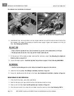
2. Loosen the jam nut on the push rod clevis, and secure the clevis to the brake pedal with a clevis pin and
rue pin
(Figure 5-21, Page 5-21)
.
3. Carefully secure the front and rear brake line flare fittings to the master cylinder. Finger-tighten the hard-
ware.
4. Use a flare-nut wrench to tighten the brake line fittings to 11 ft-lb (15 N·m).
5. Secure the reservoir hoses to the master cylinder barbed connectors.
See following NOTE.
NOTE:
The front port on the reservoir should be attached to the corresponding front port on the master cyl-
inder.
Do not allow these hoses to develop kinks or to be routed in such a way as to restrict gravity fluid
flow.
6. Fill the reservoir with brake fluid specified for this vehicle, and bleed the hydraulic brake system.
See
Bleeding the Hydraulic Brake System on page 5-22.
7. Adjust the brake pedal stroke with the clevis and master cylinder push rod threaded connection. Tighten
the jam nut to 14 ft-lb (19 N·m).
See Brake Pedal Adjustment, Section 6, Page 6-4.
8. Inspect the brake system.
See Brake System Inspection on page 5-1.
BLEEDING THE HYDRAULIC BRAKE SYSTEM
See General Warning, Section 1, Page 1-1.
The hydraulic system must be free of air. Air enters the hydraulic system whenever the system is opened and
will result in a “spongy” brake pedal.
The master cylinder controls two separate hydraulic sub-systems. The front two wheels are connected to the
front portion of the master cylinder, and the rear wheels to the rear portion. One or both sub-systems may
require bleeding, depending on where the hydraulic system was opened. To bleed both, use the following pro-
cedure, front brakes first.
1. Check the brake pedal and master cylinder push rod for proper adjustment before the brake system is
bled.
See Brake Pedal Adjustment, Section 6, Page 6-4.
2. Chock the front or rear wheels, release the park brake, and lift the vehicle with a chain hoist or floor jack.
See WARNING “Lift only one end...” in General Warning on page 1-1.
3. Place jack stands under the outer front frame or under the rear axle tubes, and lower onto stands
(Figure 5-2, Page 5-6)
.
4. Remove the cap from the master cylinder reservoir, and fill the reservoir with DOT 5 brake fluid.
5. Place, but do not tighten, the cap on the master cylinder reservoir.
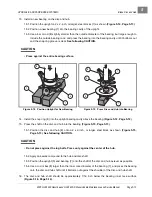
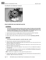
6. Connect the vacuum-type brake bleeder (Husqvarna 603 00 20-04).
• Front Brakes Only:
Connect the two hose fittings from a vacuum type brake bleeder to the top brake
bleeder valves on the back of each of the front caliper assemblies.
• Rear Brakes Only:
Connect the two hose fittings from a vacuum type brake bleeder to the brake
bleeder valves on the back of each of the rear caliper assemblies.
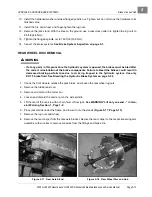
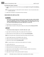
6.1. Connect an air hose to the vacuum brake bleeder. The air pressure must be regulated at 12 to 15
psi (0.827 to 1.034 Bars).
6.2. Press the handle on the brake bleeder to start the vacuum.
Содержание HUV4420
Страница 1: ... 5 5 2 4 56 56 3 3 6 3 4 3 26 5 ...
Страница 2: ......
Страница 16: ...Page xiv 2005 HUV4420 Gasoline and HUV4420 D Diesel Vehicle Maintenance and Service Manual ...
Страница 20: ...1 ...
Страница 38: ...4 ...
Страница 68: ...5 ...
Страница 74: ...6 ...


