


12
Ch.2 Site Server
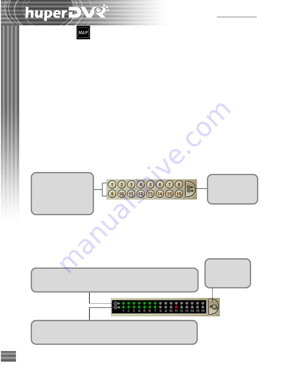
To monitor a video
camera, click its camera
number. The screen then
changes into single view,
displaying live video from
the selected camera.
Click the Switcher
button to change to
the Input/Output
Device Panel.
Click the
Switcher button
to change to the
Camera Panel.
The top row of light indicators show the connection status of input devices
such as sensors. A green light indicates that the device is connected. A red
light indicates that the device is transmitting signal to Site Server.
The bottom row of light indicators show the connection status of output
devices such as alarms. A green light indicates that the device is connected.
A red light indicates that Site Server is transmitting signal to the device.
Map button
Click the
Map
button to switch Site Server to
Map mode
. This mode shows a graphical layout of
the site being monitored, with clear indications on where the video cameras, sensors, and/or
alarms are installed. (See "Monitoring a Site in Map Mode" on page 21 for details.)
Channel Selection Panel
By default,
Video Camera
buttons are displayed at the bottom of the Site Server program
window. These buttons allow you to display a split screen in single view.
If there are input/output devices such as sensors and alarms also connected, you can easily switch
between viewing video cameras and monitoring the input/output devices.
Camera Panel
This panel provides camera buttons that are numbered in sequence and a Switcher button.
Input/Output Device Panel
Input/Output Device Panel displays light indicators that show whether the input/output devices
are connected to the Site Server.
Содержание huberDVR 2400
Страница 146: ...146 Appendix Output wiring Diagram NC Normal Close setting NO Normal Open setting...
Страница 161: ...161 DVR Using RS232 Com Port Connect to RS232 Port DVR using COM Port...
Страница 162: ...162 Appendix DVR Using USB to Connect to RS232 Com Port Connect to USB RS232 converter DVR without COM Port...
Страница 165: ...165 Input Output Pin...
Страница 169: ...169 Application Example Small Fan or TV Set under 5A IOB 0805 RO Wiring Example B Small Fan or TV Set under 5A...
Страница 182: ...182 Appendix Input Output Pin...
Страница 213: ...213 Step 4 Connect RS232 cable from the RS 232 port of converter device to the computer...
Страница 216: ...216 Appendix huperRemote Manual...


