background image

100

'(876&+‡%HWULHEVDQOHLWXQJ

7&;


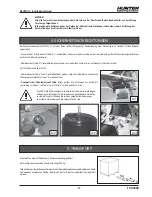
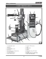
8. ÜBERSICHT ÜBER DIE BEFEHLSEINRICHTUNGEN

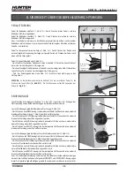
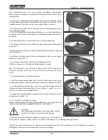
PEDALSTEUERUNG

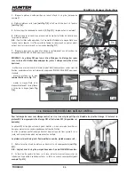
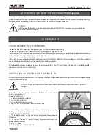
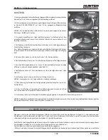
Pedal für Radheber-Hubfahrt (1, Abb. G/1): Durch Drücken dieses Pedals wird die 
Radheber-Plattform angehoben.
Pedal für Radheber-Senkfahrt (2, Abb. G/1): Durch Drücken dieses Pedals wird die 
Radheber-Plattform abgesenkt.
Anm.: Diese Pedale sind immer an der Reifenmontiermaschine installiert, auch wenn der 
Radheber nicht vorhanden ist, um eine eventuelle Nachrüstung der Maschine mit diesem 
Zubehör zu erleichtern.

Pedal für Einspannen/Lösen der Felge (3, Abb. G/1): Durch Drücken des Pedals nach 
unten erfolgt die Einspannung der Felge am Spannfutter; durch Drücken des Pedals nach 
oben wird die Felge gelöst.

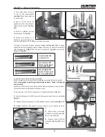
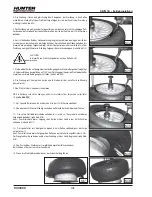
Pedal für Spannfutterdrehung (4, Abb. G/1):
- Durch leichtes Drücken des Pedals nach unten (siehe Abb. G/2) dreht das Spannfutter auf 
der ersten Geschwindigkeit im Uhrzeigersinn.
- Durch vollständiges Durchdrücken des Pedals bis zum Anschlag (siehe Abb. G/2) dreht das 
Spannfutter auf der zweiten Geschwindigkeit im Uhrzeigersinn.
- Wird das Pedal angehoben (siehe Abb. G/2), dreht das Spannfutter gegen den 
Uhrzeigersinn.

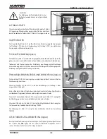
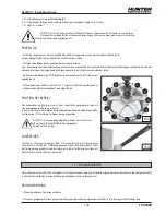
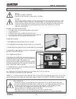
ACHTUNG: 

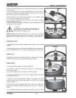
An der Reifenmontiermaschine befindet sich ein zusätzliches Pedal für die 

Drehung des Spannfutters (

6, Abb. G/3

). Die Funktionsweise entspricht derjenigen des 

Pedals (

4, Fig. G/1

).

BEDIENKONSOLE

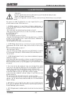
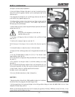
Leuchtanzeige Maschineneinschaltung (5, Abb. G/4): Signalisiert das Anliegen der 
Netzspannung an den Befehlseinrichtungen der Reifenmontiermaschine.

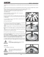
Joystick für Bewegungsabläufe der oberen Werkzeuge (9, Abb. G/4):
- Durch Drücken nach OBEN bewegt sich der obere vertikale Schlitten nach oben, wodurch 
die oberen Werkzeuge (6 und 7, Abb. G) vom Rad entfernt werden.
- Durch Drücken nach UNTEN bewegt sich der obere vertikale Schlitten nach unten, wodurch 
die oberen Werkzeuge dem Rad angenähert werden.
- Durch Drücken nach LINKS bewegt sich der horizontale Schlitten nach vorn, wodurch die 
oberen Werkzeuge dem Rad angenähert werden.
- Durch Drücken nach RECHTS bewegt sich der horizontale Schlitten nach hinten, wodurch 
die oberen Werkzeuge vom Rad entfernt werden.

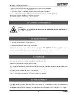
Joystick für Bewegungsabläufe der unteren Wulstabdrückscheibe (10, Abb. G/4):
- Durch Drücken nach OBEN bewegt sich der untere vertikale Schlitten nach oben, wodurch 
die untere Wulstabdrückscheibe (4, Abb. G) dem Rad angenähert wird.
- Durch Drücken nach UNTEN bewegt sich der untere vertikale Schlitten nach unten, wodurch 
die untere Wulstabdrückscheibe vom Rad entfernt wird.
- Durch Drücken nach LINKS bewegt sich der horizontale Schlitten nach vorn, wodurch die 
untere Wulstabdrückscheibe dem Rad angenähert wird.
- Durch Drücken nach RECHTS bewegt sich der horizontale Schlitten nach hinten, wodurch 
die untere Wulstabdrückscheibe vom Rad entfernt wird.
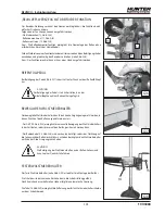
Anm.: Da sich das obere Werkzeug und die untere Wulstabdrückscheibe auf einem einzigen 
horizontalen Schlitten befinden, erfolgen die VORWÄRTS- und RÜCKWÄRTS-Bewegungen 
dieser Teile gleichzeitig bei Betätigung sowohl des oberen als auch des unteren Joysticks.

1

G/1

2

3

4

6

G/3

G/4

5

9

10

im Uhrzeigersinn 
(1 Geschw.)

0

gegen Uhrzeigersinn

im Uhrzeigersinn 
(2 Geschw.)

G/2

Содержание TCX3000

Страница 1: ...HYDRAULIQUE HYDRAULISCHE REIFENMONTIERMASCHINE DESMONTADORA DE NEUMATICOS HIDRAULICA MANUALE ISTRUZIONI 3 INSTRUCTION MANUAL 33 MANUEL D INSTRUCTIONS 63 BETRIEBSANLEITUNG 93 MANUAL DE INSTRUCCIONES 123 Form 6237 TE 01 11 TCX3000 INSTALLATION OPERATION MANUAL Copyright 2011 Hunter Engineering Company ...

Страница 2: ...the machine machinery part SeriesTCXTire Changers Machine type TCX400 Series TCX500 Series TCX600 Series TCX3000 Series Serial Number Various Applicable EC Directives 2006 42 EC 2006 95 EC 87 404 EEC 86 217 EEC 2004 108 EC Applicable Harmonized Standards EN ISO 12000 1 EN 60204 EN ISO 12000 2 Notified Body according to annex VII Not applicable name address Responsible for Not applicable Date Autho...

Страница 3: ... IDENTIFICAZIONE DELLE PARTI 9 8 IDENTIFICAZIONE DEI COMANDI 10 9 IDENTIFICAZIONE SEGNALI DI PERICOLO 13 10 CONTROLLI PRELIMINARI AL PRIMO UTILIZZO 14 11 USO 14 11 1 RUOTA STANDARD 15 11 2 RUOTE CON PNEUMATICO RUN FLAT O RIBASSATO 19 11 3 GONFIAGGIO 24 11 4 UTILIZZO DEL DISTANZIALE KOF50 OPTIONAL 25 11 5 BLOCCAGGIO RUOTE CON CANALE ROVESCIO 25 11 6 BLOCCAGGIO RUOTE SENZA FORO CENTRALE 26 12 MANUTE...

Страница 4: ...a sul sollevatore se presente 100 kg Pressione pneumatica di esercizio min 8 bar Pressione idraulica di esercizio 120 bar Peso della macchina 461 kg Livello di pressione acustica al posto di lavoro LpA 70 dB A 3 NORME DI SICUREZZA GENERALI La macchina può essere utilizzata soltanto da personale qualificato e autorizzato Unoperatores intendequalificatosehacompresoleistruzioniscrittecomunicatedalfor...

Страница 5: ...ircuito idraulico limita la massima pressione sul circuito a 110 bar Per TCX3000 con accessorio GT300 Valvola di massima pressione sul serbatoio fig A 3 montata sul serbatoio interviene in caso in cui la pressione di alimentazione pneumatica superi gli 11 bar Valvola pneumatica di sicurezza fig A 4 impedisce l azionamento del dispositivo di gonfiaggio se quest ultimo non è correttamente posizionat...

Страница 6: ...ma pari a 8 bar ATTENZIONE Non è consentito installare ed usare lo smontagomme in atmosfera esplosiva 6 2 DISIMBALLO E POSIZIONAMENTO 1 Disimballarelosmontagommecontrollandochesiainperfettecondizioni Verificare che non siano presenti danni manifesti 2 Svitare tutte le viti che fissano la macchina al pallet servendosi di un chiave esagonale da 13 mm ATTENZIONE Tenere il materiale da imballaggio fuo...

Страница 7: ...nando leggermente la fascia che viene fissata nelle sue vicinanze N B In alternativa al carrello elevatore è possibile utilizzare una gruetta o un parancodiportataidonea Inquestocasosiconsigliadiraggrupparelequattrofasce in un unico punto di sollevamento come mostrato in Fig C 4 7 Togliere le cinghie di sollevamento e rimuovere i golfari dalla carcassa 6 3 MONTAGGIO 1 Montare il supporto per il va...

Страница 8: ...bimentorichiestoeverificareselareteelettricainquestione è sufficientemente dimensionata ATTENZIONE Interventi sull impianto elettrico anche di lieve entità richiedono l opera di personale professionalmente qualificato Ogni danno derivante dalla mancata osservanza delle suddette indicazioni non sarà addebitabile al costruttore e comporterà la decadenza delle condizioni di garanzia 6 6 MONTAGGIO PED...

Страница 9: ...plo utensile revolver 7 Premi tallone fisso 8 Premi tallone mobile 9 Monitor TCX3000 optional 2 10 Telecamera TCX3000 optional 11 Specchio 12 TPM300 optional 13 Pedale di gonfiaggio 14 Manometro 15 Dispositivo gonfia tubeless GT300 optional 16 Puntatore laser 17 Pedale supplementare rotazione mandrino 18 Mozzo filettato con ghiera bloccaggio G 3 4 5 6 7 8 9 10 11 12 13 14 15 16 1 17 18 ...

Страница 10: ...gnala la presenza di tensione di rete ai comandi dello smontagomme Joystick movimenti utensili superiori 9 Fig G 4 azionato verso l ALTO muove il carrello verticale superiore verso l alto allontanando gli utensili superiori 6 e 7 Fig G dalla ruota azionatoversoilBASSOmuoveilcarrelloverticalesuperioreversoilbassoavvicinando gli utensili superiori alla ruota azionato verso SINISTRA muove il carrello...

Страница 11: ...ita sulla valvola della ruota PREMI TALLONE MOBILE Il dispositivo premitallone mobile può essere utilizzato in molteplici operazioni nelle quali sia necessario esercitare una pressione sul pneumatico La maniglia 14 Fig G 8 consente di muovere manualmente il premitallone in senso vericale in modo da essere posizionato sul pneumatico Il comando a levetta 15 Fig G 8 azionato verso il basso consente d...

Страница 12: ...effettuato alcun movimento ritornano in condizione di stand by TPM300 RILEVATORE SENSORI RUOTA optional Il dispositivo TPM 300 è in grado di identificare il tipo di sensore di pressione eventualmente presente all interno del pneumatico L interruttore 22 Fig G 11 consente di accendere posizione 1 o spegnere posizione 0 il dispositivo Sul pannello 20 Fig G 9 sono presenti i tasti funzionali per acce...

Страница 13: ...ibili o siano state rimosse sostituirle immediatamente Non utilizzare lo smontagomme se mancante di una o più targhette di pericolo Non interporre oggetti che ne ostruiscano la visione all operatore Per eventuali richieste utilizzare il codice indicato nella presente tavola ATTENZIONE Il dispositivo deve essere tenuto saldamente con entrambe le mani Non orientare MAI il dispositivo verso persone G...

Страница 14: ...mportantissime per evitare rischi di scoppio del pneumatico nella fase di tallonatura e gonfiaggio I cerchi riportano stampati sulla loro superficie i dati caratteristici di diametro larghezza numero di Hump ecc Ad es un indicazione 6Jx14H2 1 6 Indica la larghezza nominale del cerchio 2 J Indica la misura della flangia 3 14 Indica il diametro nominale del cerchio 4 H2 Indica un doppio rilievo o do...

Страница 15: ...mentiduranteleoperazionidimontaggio o smontaggio POSIZIONE DELLA VALVOLA L immaginealatomostrauncerchiomontatosulmandrinoconraffigurateleposizioni delle ore come si trattasse di un orologio Nelle varie fasi operative di seguito riportate parlando della posizione della valvola si fa SEMPRE riferimento a queste posizioni ATTENZIONE Per evitare possibili danneggiamenti al sensore di pressione se pres...

Страница 16: ...enendo il cono a contatto con la ghiera inserire il mozzo sul mandrino ruotare il mozzo in senso orario fino all innesto con il perno interno del mandrino N B Ci si accorge del corretto innesto quando il mozzo cade verticalmente nel mandrino stesso continuare la rotazione fino a che non si avverte uno scatto provocato dalla molla presente all interno del mozzo che indica l avvenuto bloccaggio 10 Pos...

Страница 17: ...na del cerchio vedi Fig L 2 Utilizzare un lubrificante specifico per pneumatici Evitare di applicare il lubrificante sul sensore se presente 10 Seguendo il profilo del cerchio muovere il disco stallonatore fino a riportarlo nella posizione iniziale 11 Utilizzando il disco stallonatore inferiore ripetere le operazioni dal punto 6 per il tallone inferiore vedi Fig L 3 NOTA Inquestafaseèpossibileagev...

Страница 18: ...emi tallone mobile posizionato a 180 rispetto all utensile per ottenere questa condizione vedi Fig M 4 8 Iniziare la rotazione in senso orario e continuare fino al completo smontaggio del primo tallone 9 Sganciare manualmente il tallone dall l uncino 10 Muovere l utensile all indietro fino a riallineare il laser al bordo del cerchio vedi Fig M 5 11 Ruotare il mandrino fino a portare la valvola in ...

Страница 19: ...nferiore NOTA Operare in modo che cerchio e pneumatico si muovano in modo solidale 10 Senzamodificarelaposizionedell utensiledimontaggioportarelavalvolaacircaore 5 11 Premere manualmente sul fianco del pneumatico a ore 3 fino a fortare il tallone all altezza del canale vedi Fig N 3 12 Iniziare la rotazione accompagnando con la mano il movimento fino al completo montaggio del tallone superiore NOTA...

Страница 20: ...opportuni controlli su pneumatico e cerchio come descritto nell apposito paragrafo a pag 14 di questo manuale 2 Procederealbloccaggiodellaruotasulmandrinooperandocomedescrittoperleruote standard nel paragrafo BLOCCAGGIO RUOTA a pag 15 di questo manuale STALLONATURA Procedereallastallonaturadelpneumaticooperandocomedescrittoperleruote standard nel paragrafo STALLONATURA a pag 16 di questo manuale S...

Страница 21: ...per portarlo in posizione di fuori lavoro 17 Sollevare il disco stallonatore inferiore fino a portarlo circa 10 mm oltre il bordo superiore del cerchio vedi Fig O 6 N B Facilitarequestaoperazionesollevandomanualmenteilpneumaticoaore6 vedi Fig O 7 18 Ruotare il mandrino in senso orario fino alla completa fuoriuscita del pneumatico dal cerchio N B Agevolarequestaoperazionesollevandocontemporaneament...

Страница 22: ...taggio ripetereleoperazioni aumentando o diminuendo la pressione esercitata dal disco premi tallone fisso 11 Portare la valvola a circa ore 4 12 Inclinare manualmente il pneumatico vedi Fig P 3 in modo da creare lo spazio necessario per il successivo inserimento dell utensile di montaggio tra cerchio e pneumatico 13 Abbassare l utensile superiore fino a portarlo dentro il cerchio di circa 30mm e a...

Страница 23: ...aproceduraoltreadesserenecessariaquandosilavoracongrossidiametri può essere consigliata sempre anche per i cerchi più piccoli MONTAGGIODELSECONDOTALLONESURUOTECONCERCHIO IN FERRO Operando su ruote ribassate o run flat autoportanti con cerchio in ferro seguire le procedure precedentemente descritte escluso il montaggio del secondo tallone La necessità di una modifica alla procedura si rende necessa...

Страница 24: ...il pedale di gonfiaggio Fig G 7 6 Tallonare introducendo aria a brevi tratti verificando continuamente negli intervalli la pressione sul manometro 16 Fig G 9 fino a che i talloni non siano posizionati nelle rispettive sedi Particolare cura ed attenzione deve essere posta nella tallonatura di gomme su cerchi dotati di bordino antistallonatura HUMP DOUBLE HUMP etc 7 Prosequire sempre introducendo ar...

Страница 25: ...u ruote con qualsiasi numero di fori di fissaggio Sulla flangia può infatti essere montato un numero di pioli corrispondente al numero di fori presente sul cerchio o un suo multiplo La flangia è dotata di 6 pioli qualora si renda necessario variarne il numero operare nel modo seguente N B Il piolo con la vite grigia contrassegnato dal numero 0 non deve MAI essere rimosso 1 Rimuovere gli altri piol...

Страница 26: ...gio come descritto nel paragrafoBLOCCAGGIORUOTAper le ruote standard posizionare la flangia sulla ruota come mostrato in Fig T 8 montareilmozzofilettatoebloc care con la ghiera direttamente sulla flangia vedi Fig T 8 11 6 BLOCCAGGIO RUOTE SENZA FORO CENTRALE Per il bloccaggio di ruote senza foro centrale o dove questo foro risulti più piccolo del diametro del perno di bloccaggio è necessario dispo...

Страница 27: ...o fino all innesto con il perno interno del mandrino N B Ci si accorge del corretto innesto quando il mozzo cade verticalmente nel mandrino stesso Continuare la rotazione fino a che non si avverte uno scatto provocato dalla molla presente all interno del mozzo che indica l avvenuto bloccaggio 8 Fissare la flangia sul mandrino premendo il pedale di bloccaggio 3 Fig G 1 9 Con l apposito calibro rilevar...

Страница 28: ...HGconviscositàISO VG 32 ad esempio ESSO Febis K 32 MOBIL Vacouline Oil 1405 KLUBER Airpress 32 Riavvitare la vaschetta 3 CONTROLLARE periodicamente ogni 2 3 giorni il corretto funzionamento del gruppo lubrificatore 4 Fig R 3 Agire sul comando del premi tallone fisso verficando che ogni 5 6 corse complete del braccio cadaunagocciadiolionellacupolettatrasparente 6 Fig R 3 dellubrificatore In caso co...

Страница 29: ...fonte di alimentazione 2 Movimentare operando come descritto nel paragrafo DISIMBALLO E POSIZIONAMENTO a pag 6 del presente manuale 3 Ricollegare lo smontagomme alle sue fonti di alimentazione e controllare il corretto funzionamento dei comandi 15 ACCANTONAMENTO In caso di accantonamento per lungo periodo è necessario Scollegare lo smontagomme da ogni sua fonte di alimentazione Pulire ed ingrassar...

Страница 30: ...vere informazioni sulle modalità di raccolta Al momento dell acquisto di questo prodotto il vostro distributore vi informerà inoltre della possibilità di rendere gratuitamente un altro apparecchio a fine vita a condizione che sia di tipo equivalente ed abbia svolto le stesse funzioni del prodotto acquistato Uno smaltimento del prodotto in modo diverso da quanto sopra descritto sarà passibile delle...

Страница 31: ... o schiacciato RIMEDI 1 Ripristinare l alimentazione dalla sorgente di aria compressa 2 Ripristinare il passaggio dell aria ed eventualmente sostituire il tubo se risultasse danneggiato INCONVENIENTE Si nota un rallentamento nei movimenti degli utensili nonché una scarsa potenza CAUSE 1 L olio nel serbatoio della centralina oleodinamica è sotto il livello minimo RIMEDI 1 Consultare il paragrafo Ma...

Страница 32: ...32 7 12 0DQXDOH G XVR 7 ...

Страница 33: ...L CONNECTION 38 6 6 FITTING THE WHEEL LIFT 38 7 KEY TO PARTS 39 8 KEY TO CONTROLS 40 9 KEY TO HAZARD SIGNS 43 10 CHECKS BEFORE FIRST USE 44 11 USE 44 11 1 STANDARD WHEEL 45 11 2 WHEELS WITH RUN FLAT OR LOW PROFILE TYRES 49 11 3 INFLATION 54 11 4 USING THE KOF50 SPACER OPTIONAL 55 11 5 CLAMPING WHEELS WITH REVERSE RIM 55 11 6 CLAMPING CLOSED CENTRE WHEELS 56 12 MAINTENANCE 58 13 FIREFIGHTING REGULA...

Страница 34: ...lift if installed 100 kg Pneumatic operating pressure min 8 bar Hydraulic operating pressure 120 bar Weight of machine 461 kg Acoustic pressure level in working position LpA 70 dB A 3 GENERAL SAFETY REGULATIONS The machine must only be operated by authorised skilled personnel In order to be classified as skilled an operator must have understood the supplier s written instructions attended a specif...

Страница 35: ...fig A 4 prevents operation of the inflation device if it is not correctly positioned on the wheel WARNING Tampering with or removing the safety devices constitutes a breach of European regulations and relieves the producer from liability for consequent or related damage A 1 A 2 A 3 5 TRANSPORT The machine is supplied in cardboard packaging on a pallet The machine in its packaging weighs 490 kg Handl...

Страница 36: ...vingan operating pressure of at least 8 bar WARNING The machine must not be operated in an explosive atmosphere 6 2 UNPACKING AND POSITIONING 1 Unpack the machine and check that it is in perfect condition Inspect for any obvious damage 2 Unscrew all the screws which hold the machine on the pallet with the aid of a 13 mm spanner WARNING Keep packaging material out of reach of children because it ma...

Страница 37: ...ling which is to be fixed next to it slightly N B A small crane or hoist with suitable lifting capacity can be used instead of a fork lift truck In this case the four slings should be attached to a single lifting point as shown in Fig C 4 7 Remove the lifting slings and remove the eye bolts from the machine body 6 3 ASSEMBLY 1 Fit the grease cup support using the screws supplied with the machine s...

Страница 38: ...arofthetyrechangerforthepowerabsorptionrequired andcheckthatthemainssystemavailableissuitably rated WARNING Any work on the electrical system however minor must be done by qualified staff The manufacturer will not be liable for any damage deriving from failure to follow the above instructions which will also cause the immediate expiry of the warranty 6 6 FITTING THE WHEEL LIFT if supplied 1 Operat...

Страница 39: ...revolver tool 7 Fixed bead presser 8 Mobile bead presser 9 TCX3000 video screen optional 2 10 TCX3000 camera optional 11 Mirror 12 TPM300 optional 13 Inflation pedal 14 Pressure gauge 15 GT300 Tubeless tyre inflation device optional 16 Laser pointer 17 Additional chuck rotation pedal 18 Threaded hub with clamping ring nut G 3 4 5 6 7 8 9 10 11 12 13 14 15 16 1 17 18 ...

Страница 40: ...tes that the circuit supplying power to the tyre changer controls is powered up Upper tool operating joystick 9 Fig G 4 push UP to move the top vertical carriage upward moving the upper tools 6 and 7 Fig G away from the wheel pushDOWNtomovethetopverticalcarriageupward movingtheuppertoolstowards the wheel pushLEFTtomovethehorizontalcarriageforward movingtheuppertoolstowards the wheel pushRIGHTtomov...

Страница 41: ... that the head is fitted into the wheel valve correctly MOBILE BEAD PRESSER Themobilebeadpressercanbeusedinalargenumberofproceduresinwhichpressure has to be applied to the tyre The handle 14 Fig G 8 allows the bead presser to be moved vertically by hand to position it on the tyre The control lever 15 Fig G 8 is moved down to press on the wall of the tyre or raised to lift the bead presser at the e...

Страница 42: ...status if 30 seconds pass without performance of any movements TPM300 TYRE PRESSURE MONITOR optional TheTPM 300 device is able to identify the type of the pressure sensor if any installed inside the tyre The switch 22 Fig G 11 can be used to switch the device on set on 1 or off set on 0 The panel 20 Fig G 9 has the function keys used to access the various programme functions and the alphanumerical...

Страница 43: ... signs are illegible or missing replace them immediately Do not use the tyre changer if one or more warning signs are missing Never place anything in a position where it may obstruct the operator s view When ordering state the code shown below WARNING The device must be held firmly in both hands NEVER point the device at people G 14 24 ...

Страница 44: ... that the tyre may burst during the bead insertion and inflation stage Rims have their nominal diameter width Hump number etc data stamped on their surfaces E g a marking 6Jx14H2 1 6 Indicates the nominal width of the rim 2 J Indicates the flange size 3 14 Indicates the nominal diameter of the rim 4 H2 Indicates a double hump Tyres are marked with a large amount of information including dimensions...

Страница 45: ...ightlead to damage during mounting or demounting operations VALVE POSITION Theillustrationshowsarimfittedonthechuck showingthepositionsofthehours as if on a clock In the various operating stages described below when the valve position is mentioned reference is ALWAYS made to these positions WARNING To avoid the risk of damage to the pressure sensor if installed the valve must ALWAYS be set in the ...

Страница 46: ...huck turn the hub clockwise by hand until it mates with the pin inside the chuck N B You will realise that the parts have engaged correctly when the hub drops vertically into the chuck Keep rotating until the spring inside the hub clicks into place 10 Place the cone touching the rim perfectly centred on the well in the middle 11 Tighten the ring nut ratchet to bring it into position against the co...

Страница 47: ...to the sensor if any 10 Following the profile of the rim move the bead breaker disc until it is back in the starting position 11 Usingthebottombeadbreakerdisc repeattheoperationsfrompoint6forthe bottom bead see Fig L 3 NOTE In this stage a better view of the operation can be obtained with the aid of the mirror or if available the camera which displays the images on the video screen N B Both the up...

Страница 48: ...o the tool to achieve this see Fig M 4 8 Start clockwise rotation and continue until the first bead is completely demounted 9 Release the bead from the hook by hand 10 Move the tool back until the laser is realigned with the edge of the rim see Fig M 5 11 Turn the chuck until the valve is at the 12 o clock position 12 Raise the top carriage completely until it is in the out of use position 13 Lift...

Страница 49: ...nting tool move the valve to about 5 o clock 11 Pressdownthesidewallofthetyrebyhandat3o clocktoforcethebeaddown to the height of the well see Fig N 3 12 Start rotation following the motion with one hand until the top bead is completely mounted NOTE If it is difficult to perform these operations by hand the mobile bead presser can always be used placed at 3 o clock see Fig N 4 11 2 WHEELS WITH RUN ...

Страница 50: ...or standard wheels in the WHEEL CLAMPING section on page 45 of this manual BEAD BREAKING Break the tyre bead proceeding as described for standard wheels in the BEAD BREAKING section on page 46 of this manual DEMOUNTING 1 Move the lower bead breaker disc away to the rest position 2 Turn the multiple tool revolver to bring the hook tool into the working position 3 Turn the chuck until the valve is a...

Страница 51: ...nd at 6 o clock see Fig O 7 18 Turn the chuck clockwise until the tyre has come completely out of the rim N B Facilitate this operation by simultaneously lifting the bottom of the tyre at about 2 o clock and guiding its rotation see Fig O 8 19 Make a thorough inspection of the pressure sensor if any Replace it if damage is found 20 Move the lower bead breaker disc away to the rest position MOUNTIN...

Страница 52: ... the upper tool until it is about 30 mm inside the rim and a few mm from its outside edge Fit the plastic guard on the rim placing it at about 3 o clock see Fig P 4 14 Place the mobile bead presser at about 2 o clock and press gently see Fig P 4 15 Turn the chuck clockwise When the mobile bead presser is at about 5 o clock increase the pressure until the bead is aligned with the well see Fig P 5 W...

Страница 53: ...king on low profile or self supporting run flat wheels with steel rim follow the procedures described above except for mounting of the second bead Achangetotheprocedureisrequiredbecausesomesteelrimsonthemarkethaveverysharpouteredgeswhichmightdamagethetyre in the traction points especially during insertion of the second bead To avoid these risks proceed as described below 1 After mounting the first...

Страница 54: ...ecessary 5 Press the inflation pedal Fig G 6 6 Insert the bead supplying air in short bursts and constantly checking the pressure on the pressure gauge 16 Fig G 8 in the intervals between bursts until the beads have fitted into their seats Particular care and attention must be paid when inserting tyre beads on rims which have a hump to hold the bead in place HUMP DOUBLE HUMP etc 7 Continue still s...

Страница 55: ...holes The flange can be fitted with a number of pegs equal to the number of holes in the rim or a multiple of this number The flange comes complete with 6 pegs when the number has to be changed proceed as follows N B The peg with the grey screw marked with the number 0 must NEVER be removed 1 Remove the other pegs on the flange by undoing their screws see Fig T 1 2 Replace the number of pegs necessary...

Страница 56: ...HEEL CLAMPING section for standard wheels Place the flange on the wheel as shown in Fig T 8 Fit the threaded hub and use the ring nut to clamp it directly onto the flange see Fig T 8 11 6 CLAMPING CLOSED CENTRE WHEELS For clamping closed centre wheels or wheels where the central hole is smaller than the diameter of the clamping pin the FRF flange the special MFC clamping hub and the KOF spacer all op...

Страница 57: ...hand until it mates with the pin inside the chuck N B You will realise that the parts have engaged correctly when the hub drops vertically into the chuck Keep rotating until the spring inside the hub clicks into place 8 Fix the flange onto the chuck by pressing the clamping pedal 3 Fig G 1 9 Use the gauge provided to measure the distance between two holes in the rim see Fig U 6 11 Set the same dist...

Страница 58: ...iscosity ISO VG 32 for example ESSO Febis K 32 MOBIL Vacouline Oil 1405 KLUBER Airpress 32 Screw the cup back into place 3 Make a regular CHECK every 2 3 days that the lubricator unit is functioning correctly 4 Fig R 3 Operate the control of the fixed bead presser checking that at every 5 6 arm travel strokes a drop of oil falls into the clear cup 6 Fig R 3 of the lubricator Otherwise adjust the l...

Страница 59: ...described in the UNPACKING AND POSITIONING section on page 36 of this manual 3 Reconnect the tyre changer to its energy sources and check that the controls are operating correctly 15 STORAGE If the tyre changer is to be out of use for some time proceed as follows Disconnect the tyre changer from all power sources Clean and grease the chuck and the ways of the carriages horizontal and vertical whic...

Страница 60: ... information on the collection arrangements When buying this new product your distributor will also inform you of the possibility to return free of charge another end of life equipment as long as it is of equivalent type and has fulfilled the same functions as the supplied equipment A disposal of the product different from what described above will be liable to the penalties prescribed by the nati...

Страница 61: ...shed SOLUTIONS 1 Restore the compressed air supply from source 2 Adjust to ensure air can pass and replace the hose if damaged PROBLEM You notice that the tool moves more slowly and power levels are low CAUSES 1 The oil level in the hydraulic power unit is below the minimum level SOLUTIONS 1 Refer to the Maintenance section for instructions on topping up with oil After topping up with oil the air ...

Страница 62: ...62 1 6 QVWUXFWLRQV PDQXDO 7 ...

Страница 63: ...LEMENT ÉLÉVATEUR 68 7 IDENTIFICATION DES PARTIES 69 8 IDENTIFICATION DES COMMANDES 70 9 IDENTIFICATION DES SIGNAUX DE DANGER 73 10 CONTRÔLES PRÉLIMINAIRES À LA PREMIÈRE UTILISATION 74 11 UTILISATION 74 11 1 ROUE STANDARD 75 11 2 ROUES AVEC PNEU RUN FLAT OU SURBAISSÉ 79 11 3 GONFLAGE 84 11 4 UTILISATION DE L ENTRETOISE KOF50 EN OPTION 85 11 5 BLOCAGE DES ROUES À CREUX RENVERSÉ 85 11 6 BLOCAGE DES R...

Страница 64: ... le cas échéant 100 kg Pression pneumatique de service min 8 bar Pression hydraulique de service 120 bar Poids de la machine 461 kg Niveau de pression acoustique d émission au poste de travail LpA 70 dB A 3 NORMES DE SÉCURITÉ GÉNÉRALES Seul le personnel qualifié est autorisé à utiliser la machine Un opérateur est qualifié s il a compris les instructions écrites transmises par le fournisseur qu il ...

Страница 65: ...e si ce dernier n est pas correctement positionné sur la roue ATTENTION l élimination ou le forçage des dispositifs de sécurité constituent une violation des normes européennes Dans ce cas le fabricant n encourt aucune responsabilité pour tous dommages provoqués ou causés par ces actions A 1 A 2 A 3 5 TRANSPORT La machine est livrée dans une caisse palette en carton Le poids de la machine emballée...

Страница 66: ...minimum de 8 bars ATTENTION Il est interdit d installer et d utiliser le démonte pneu en atmosphère explosive 6 2 DÉBALLAGE ET MISE EN PLACE 1 Déballer le démonte pneu et s assurer qu il est en parfaite condition Vérifier qu il ne présente pas de dégâts apparents 2 À l aide d une clé hexagonale de 13 mm dévisser toutes les vis qui retiennent la machine sur la palette ATTENTION Mettre le matériau d...

Страница 67: ...ixée près de ce groupe N B à défaut de chariot élévateur il est possible d utiliser une petite grue ou un palan de capacité appropriée Danscecas ilestrecommandéderegrouperlesquatreélinguesenunseulpointde levage comme le montre la Fig C 4 7 Enlever les élingues de levage et retirer les pitons à œil de la carcasse 6 3 MONTAGE 1 Monter le support du pot graisse à pneu à l aide des vis fournies avec l...

Страница 68: ...rique est suffisamment dimensionné ATTENTION Toute intervention portant sur l installation électrique même banale doit être effectuée par un personnel professionnellement qualifié Le fabricant ne saurait être tenu pour responsable des dommages provoqués par le non respect des instructions ci dessus En outre l inobservation de ces instructions entraîne la nullité de la garantie 6 6 MONTAGE CHEMIN D...

Страница 69: ... Triple outil revolver 7 Presse talon fixe 8 Presse talon mobile 9 Écran TCX3000 en option 2 10 Caméra TCX3000 en option 11 Miroir 12 TPM300 en option 13 Pédale de gonflage 14 Manomètre 15 Dispositif de gonflage tubeless GT300 en option 16 Pointeur laser 17 Pédale supplémentaire de rotation du mandrin 18 Moyeu fileté avec bague de blocage G 3 4 5 6 7 8 9 10 11 12 13 14 15 16 1 17 18 ...

Страница 70: ...mouvements dispositifs supérieurs 9 Fig G 4 le pousser vers le HAUT pour déplacer le chariot vertical supérieur vers le haut et éloigner les dispositifs supérieurs 6 et 7 Fig G de la roue le pousser vers le BAS pour déplacer le chariot vertical supérieur vers le bas et rapprocher les dispositifs supérieurs de la roue lepousserverslaGAUCHEpourdéplacerlechariothorizontalversl avantetrapprocher les d...

Страница 71: ...ue l embout est bien mis sur la valve de la roue PRESSE TALON MOBILE Le presse talon mobile peut être utilisé à chaque fois qu il est nécessaire d exercer une pression sur le pneu Le levier 14 Fig G 8 permet de déplacer manuellement le presse talon dans le sens vertical pour bien le positionner sur le pneu En position basse le levier 15 Fig G 8 permet d exercer une pression sur le flanc du pneu et...

Страница 72: ...uvement des dispositifs Si aucun mouvement n est effectué pendant 30 secondes ils se mettent en position de veille TPM300 DÉTECTEUR CAPTEURS ROUE en option Le dispositif TPM 300 est en mesure de reconnaître le type de capteur de pression éventuellement monté à l intérieur du pneu L interrupteur 22 Fig G 11 permet d allumer position 1 ou d éteindre position 0 le dispositif Le panneau 20 Fig G 9 com...

Страница 73: ...r le démonte pneu s il manque une ou plusieurs plaques signaux de danger Ne pas gêner la vue de l opérateur avec des objets Pour toute demande utiliser le code reporté dans ce tableau les 2 touches 24 Fig G 14 on obtient la sortie d un puissant jet d air qui permet un entalonnage rapide des pneumatiques sur les jantes ATTENTION Le dispositif doit être tenu fermement à deux mains Ne JAMAIS pointer ...

Страница 74: ...t pas endommagés ATTENTION ces opérations sont très importantes pour éviter tout risque d éclatement du pneu en cours de talonnage et de gonflage Les caractéristiques concernant le diamètre la largeur le nombre d épaulement hump etc sont imprimées sur les jantes Par ex l inscription 6Jx14H2 1 6 Indique la largeur nominale de la jante 2 J Indique la taille du flasque 3 14 Indique le diamètre nomina...

Страница 75: ...e température inférieure pourraitendommagerlepneupendantlesopérationsdemontageoudedémontage POSITION DE LA VALVE L image ci contre représente une jante montée sur le mandrin et les positions des heures comme s il s agissait d une montre Pour les phases opérationnelles ci après ces positions servent TOUJOURS de base pour décrire la position de la valve ATTENTION pour éviter d endommager le capteur ...

Страница 76: ... avec la bague insérer le moyeu sur le mandrin tourner le moyeu en sens horaire jusqu à l assemblage avec le pivot intérieur du mandrin N B On s aperçoit que l assemblage est correct lorsque le moyeu tombe verticalement dans le mandrin continuer la rotation jusqu à ce que l on entende un déclic provoqué par le ressort présent à l intérieur du moyeu qui indique que le blocage a eu lieu 10 Mettre le...

Страница 77: ...ilrevienne à sa position de départ 11 Refaire les opérations à partir du point 6 avec le disque détalonneur inférieur pour le talon inférieur voir Fig L 3 REMARQUE pour mieux voir les différentes opérations à effectuer l opérateur peut s aider du miroir ou le cas échéant de la caméra qui permet de visualiser les images sur l écran N B le disque détalonneur supérieur comme le disque détalonneur inf...

Страница 78: ... le sens des aiguilles d une montre et continuer jusqu à ce que le premier talon soit complètement démonté 9 Retirer manuellement le talon du crochet 10 Déplacer l outil vers l arrière jusqu à ce que le laser se réaligne avec le bord de la jante voir Fig M 5 11 Faire pivoter le mandrin jusqu à ce que la valve se trouve à 12 heures 12 Soulever complètement le chariot supérieur pour le dégager de sa...

Страница 79: ...qu à ce que le talon inférieur soit complètement monté REMARQUE travailler de façon à ce que la jante accompagne le mouvement du pneu et vice versa 10 Sans modifier la position du dispositif de montage mettre la valve à 5 heures environ 11 Appuyer manuellement sur le flanc du pneu à 3 heures pour amener le talon à la hauteur du creux voir Fig N 3 12 Commencer à faire tourner et accompagner le mouv...

Страница 80: ...a jante BLOCAGE DE LA ROUE 1 Faire tous les contrôles nécessaires sur le pneu et la jante selon les instructions données au paragraphe de la page 74 de ce manuel 2 Bloquer la roue sur le mandrin selon les instructions données pour les roues standards au paragraphe BLOCAGE ROUE de la page 75 de ce manuel DÉTALONNAGE Procéder au détalonnage du pneu selon les instructions données pour les roues stand...

Страница 81: ...lever complètement le chariot supérieur pour le dégager de sa position de travail 17 Soulever le disque détalonneur inférieur jusqu à ce qu il soit à 10 mm environ au dessus du bord supérieur de la jante voir Fig O 6 N B soulever manuellement le pneu à 6 heures voir Fig O 7 pour faciliter cette opération 18 Fairepivoterlemandrindanslesensdesaiguillesd unemontrejusqu àcequelepneu sorte complètement...

Страница 82: ... refaire les opérations en augmentant ou en diminuant la pression exercée par le disque pousse talon fixe 11 Mettre la valve à 4 heures environ 12 Incliner manuellement le pneu voir Fig P 3 afin d avoir l espace nécessaire pour introduire le dispositif de montage entre la jante et le pneu 13 Abaisser le dispositif supérieur jusqu à l engager d environ 30 mm dans la jante à quelquesmmdesonbordextéri...

Страница 83: ...B Nonseulementcetteprocédureestnécessaireencasdejantesdegranddiamètre mais elle peut aussi être recommandée pour les jantes plus petites MONTAGE DU DEUXIÈME TALON SUR LES ROUES AVEC JANTE EN FER Pour les interventions sur les pneus surbaissés ou Run Flat autoporteurs avec jante en fer appliquer les procédures décrites ci dessus à l exception de celle concernant le montage du deuxième talon Laprocé...

Страница 84: ...fisamment lubrifiés lubrifier le cas échéant 5 Enfoncer la pédale de gonflage Fig G 6 6 Mettre en place le talon et insuffler de l air par petites pressions tout en vérifiant d un intervalle à l autre le manomètre 16 Fig G 8 jusqu à ce que les talons se glissent dans leur logement Faire particulièrement attentionlorsdumontagedutalonencasdepneusavecjantesprésentant un profil anti déjantage HUMP DOU...

Страница 85: ...ravailler sur des roues présentant un nombre quelconque de trous de fixation En effet le plateau peut être équipé d autant de pivots que de trous présents sur la jante ou d un nombre de pivots correspondant au multiple Le plateau est muni de 6 pivots Pour modifier ce nombre procéder comme suit N B Le pivot avec la vis grise marqué du numéro 0 ne doit JAMAIS être enlevé 1 Retirer les autres pivots du...

Страница 86: ...formément aux instructions du paragraphe BLOCAGE DE LA ROUE pour roues standard placer le plateau sur la roue comme illustré sur la Fig T 8 monter le moyeu fileté et le bloquer directement sur le plateau à l aide de la bague voir Fig T 8 11 6 BLOCAGE DES ROUES SANS ALÉSAGE CENTRAL Pour le blocage de roues sans alésage central ou si ce trou est plus petit que le diamètre du pivot de blocage il faut ...

Страница 87: ...avec le pivot intérieur du mandrin N B Ons aperçoitquel assemblageestcorrect lorsquelemoyeu tombe verticalement dans le mandrin Continuer la rotation jusqu à ce que l on entende un déclic provoqué par le ressort présent à l intérieur du moyeu qui indique que le blocage a eu lieu 8 Fixer le plateau sur le mandrin en appuyant sur la pédale de blocage 3 Fig G 1 9 Avec le calibre prévu à cet effet mes...

Страница 88: ...tiques de grade ISOHGavecviscositéISO VG 32 par exemple ESSO Febis K 32 MOBILVacouline Oil 1405 KLUBER Airpress 32 Revisser le carter 3 CONTRÔLER régulièrement tous les 2 3 jours le bon fonctionnement du groupe lubrificateur 4 Fig R 3 Activer la commande du presse talon fixe et vérifier qu une goutte d huile tombe sur la coupole transparente 6 Fig R 3 du lubrificateur tous les 5 6 tours complets d...

Страница 89: ...ébrancher le démonte pneu de toute source d alimentation 2 Déplacerledémonte pneuselonlesinstructionsdonnéesauparagraphe DÉBALLAGEETMISEENPLACE delapage66decemanuel 3 Rebrancher l alimentation du démonte pneu et vérifier le bon fonctionnement des commandes 15 REMISAGE En cas de remisage du démonte pneu pendant une longue période l opérateur doit Débrancher le démonte pneu de toute source d aliment...

Страница 90: ... et électroniques organisent des systèmes de récolte et de retraitement desdits appareils Au terme de la vie du produit adressez vous à votre distributeur qui vous fournira tout renseignement sur les modalités de récolte du pro duit Lorsdel achatdecetappareil votredistributeurvousinformeraquantàlapossibilitéderendregratuitementunappareilobsolètedemême type et servant aux mêmes fonctions L éliminat...

Страница 91: ...rasé SOLUTIONS 1 Rétablir l alimentation du réseau à air comprimé 2 Rétablir le passage de l air et remplacer éventuellement le tuyau endommagé PROBLÈME L opérateur remarque un ralentissement des mouvements des dispositifs et une faible puissance RAISONS 1 Le niveau d huile du réservoir du distributeur oléohydraulique est sous le minimum SOLUTIONS 1 Consulter le paragraphe Maintenance pour ajouter...

Страница 92: ...92 5 1d 6 0DQXHO G LQVWUXFWLRQV 7 ...

Страница 93: ...ENTEILE 99 8 ÜBERSICHT ÜBER DIE BEFEHLSEINRICHTUNGEN 100 9 GEFAHRENSCHILDER 103 10 KONTROLLEN VOR DER ERSTINBETRIEBNAHME 104 11 GEBRAUCH 104 11 1 STANDARDRÄDER 105 11 2 RÄDER MIT RUNFLAT ODER NIEDERQUERSCHNITTSREIFEN 109 11 3 REIFENFÜLLEN 114 11 4 VERWENDUNG DES DISTANZSTÜCKS KOF50 OPTION 115 11 5 EINSPANNUNG VON RÄDERN MIT VERKEHRTEM FELGENBETT 115 11 6 EINSPANNUNG VON RÄDERN OHNE MITTELLOCH 116 ...

Страница 94: ...eumatischer Betriebsdruck min 8 bar Hydraulischer Betriebsdruck 120 bar Maschinengewicht 461 kg Schalldruckpegel am Arbeitsplatz LpA 70 dB A 3 ALLGEMEINE SICHERHEITSNORMEN Die Maschine darf nur von einem autorisierten und qualifizierten Bediener benutzt werden EinBedienergiltalsqualifiziert wennerdieschriftlichenAnweisungendesZulieferersverstandenundeinespezifischeSchulungabsolvierthatsowie dieVor...

Страница 95: ...richtung verhindert sollte diese nicht korrekt am Rad positioniert sein ACHTUNG Die Entfernung bzw der Umbau der Sicherheitsvorrichtungen stellen eineVerletzung der EU Normen dar und entheben den Hersteller von der Haftung für Schäden die von den ausgeführten Änderungen verursacht werden oder auf diese zurückzuführen sind A 1 A 2 A 3 5 TRANSPORT Die Maschine wird auf Paletten mit Kartonverpackung ...

Страница 96: ...zung der Reifenmontiermaschine in explosionsfähiger Atmosphäre ist verboten 6 2 AUSPACKEN UND AUFSTELLUNG 1 BeimAuspackenderReifenmontiermaschinesicherstellen dassdiesesichineinwandfreiem Zustand befindet Überprüfen ob sichtbare Schäden zu verzeichnen sind 2 Alle Schrauben zur Befestigung der Maschine an der Palette mit einem 13 mm Sechskantschlüssel ausdrehen ACHTUNG DasVerpackungsmaterial stets ...

Страница 97: ...tzen indem man das Band das in dessen Nähe befestigt wird leicht neigt Anm Als Alternative zum Gabelstapler kann zum Anheben ein kleiner Kran oder ein Flaschenzug mit geeigneterTragfähigkeit verwendet werden IndiesemFallempfiehltsichdieZusammenführungdervierHebebänderaneinemeinzigen Hebepunkt wie in Abb C 4 gezeigt 7 Die Hebebänder entfernen und die Ringschrauben vom Gehäuse ausdrehen 6 3 MONTAGE ...

Страница 98: ...rStromaufnahmeablesenundprüfen obdasin Frage kommende Stromnetz hierfür entsprechend ausgelegt ist ACHTUNG Selbst geringfügige Eingriffe an der elektrischen Anlage dürfen ausschließlich durch qualifiziertes Fachpersonal vorgenommen werden Für Schäden die auf die Nichtbeachtung der oben aufgeführten Hinweise zurückzuführen sind übernimmt der Hersteller keinerlei Haftung zudem ist hierbei der Verfal...

Страница 99: ...ug mit dreifacher Funktion 7 FesterWulstniederhalter 8 BeweglicherWulstniederhalter 9 Monitor TCX3000 Option 2 10 Telekamera TCX3000 Option 11 Spiegel 12 TPM300 Option 13 Füllpedal 14 Manometer 15 Tubeless Füllvorrichtung GT300 Option 16 Laserzeiger 17 Zusätzliches Pedal für Spannfutterdrehung 18 Gewindenabe mit Spannmutter G 3 4 5 6 7 8 9 10 11 12 13 14 15 16 1 17 18 ...

Страница 100: ...ng an den Befehlseinrichtungen der Reifenmontiermaschine Joystick für Bewegungsabläufe der oberenWerkzeuge 9 Abb G 4 DurchDrückennachOBENbewegtsichderoberevertikaleSchlittennachoben wodurch die oberenWerkzeuge 6 und 7 Abb G vom Rad entfernt werden DurchDrückennachUNTENbewegtsichderoberevertikaleSchlittennachunten wodurch die oberenWerkzeuge dem Rad angenähert werden DurchDrückennachLINKSbewegtsich...

Страница 101: ...rrekt am Radventil eingefügt ist BEWEGLICHER WULSTNIEDERHALTER DerbeweglicheWulstniederhalterkannfürzahlreicheVorgängeeingesetztwerden in denen Druck auf den Reifen ausgeübt werden muss Der Griff 14 Abb G 8 ermöglicht die manuelle Bewegung des Wulstniederhalters in der Vertikalen sodass dieser auf den Reifen positioniert werden kann Der Bedienhebel 15 Abb G 8 wird nach unten betätigt sodass das We...

Страница 102: ...kzeugs erfolgt deren Rückstellung auf Standby TPM300 RADSENSOREN ERFASSUNGSVORRICHTUNG Option DieVorrichtungTPM300istinderLage deneventuellinnerhalbdesReifensinstallierten Drucksensortyp zu erfassen Über den Schalter 22 Abb G 11 wird die Vorrichtung ein Stellung 1 oder ausgeschaltet Stellung 0 Auf der Blende 20 Abb G 9 befinden sich die Funktionstasten für den Zugriff auf die verschiedenen Program...

Страница 103: ... Die Nutzung der Reifenmontiermaschine beim Fehlen eines oder mehrerer Gefahrenschilder ist verboten Keine Gegenstände an der Reifenmontiermaschine positionieren die die Übersicht des Bedieners beeinträchtigen können Für eventuelle Bestellungen sind stets die in der Übersicht aufgeführten Art Nr anzugeben ACHTUNG Die Vorrichtung muss fest mit beiden Händen gegriffen werden Sie darf NIEMALS gegen P...

Страница 104: ... Schäden aufweisen ACHTUNG Aufgrund der Platzgefahr des Reifens in der Aufzieh und Füllphase sind diese Kontrollen von größter Wichtigkeit An den Felgen sind die jeweiligen Kenndaten z B Durchmesser Breite Anzahl Humps usw aufgedruckt Beispiel Felge 6Jx14H2 1 6 gibt die Nennbreite der Felge an 2 J ist das Maß des Flansches 3 14ist der Nenndurchmesser der Felge 4 H2 gibt an dass zwei Höcker oder Hu...

Страница 105: ... C liegt Eine tiefere Temperatur kann zu Schäden während der Montage oder Demontage führen POSITION DESVENTILS Das nebenstehende Bild zeigt eine auf dem Spannfutter eingespannte Felge mit Stundenangaben analog zu einer Zeituhr Indenverschiedenen nachfolgendbeschriebenenArbeitsphasenwirdhinsichtlichder Ventilposition STETS auf diese Positionen Bezug genommen ACHTUNG ZurVermeidung möglicher Schäden ...

Страница 106: ... Abb I 2 Den Kegel direkt an die Spannmutter halten und währenddessen die Nabe am Spannfutter einfügen Die Nabe im Uhrzeigersinn drehen bis das Einkuppeln mit dem internen Stift des Spannfutters erfolgt Anm Man erkennt das korrekte Einkuppeln daran dass die Nabe vertikal in das Spannfutter fällt Weiter drehen bis man ein Einrasten vernimmt das durch die Feder innerhalb der Nabe hervorgerufen wird ...

Страница 107: ...seite der Felge sorgfältig geschmiert werden siehe Abb L 2 HierzueinspeziellesSchmiermittelfürReifenverwenden Daraufachten dassderSensor falls vorhanden nicht mit Schmiermittel verunreinigt wird 10 Dem Felgenprofil folgend die Wulstabdrückscheibe weiter bewegen bis sie die Ausgangsstellung wieder erreicht 11 UnterVerwendungderunterenWulstabdrückscheibedieArbeitsschritteabPunkt6fürden unteren Reife...

Страница 108: ...alter einsetzen um diese Bedingung herzustellen siehe Abb M 4 8 Die Drehung im Uhrzeigersinn starten und fortsetzen bis der erste Wulst vollständig demontiert ist 9 DenWulst mit der Hand vom Haken lösen 10 Das Werkzeug nach hinten bewegen bis der Laser wieder auf das Felgenhorn ausgerichtet ist siehe Abb M 5 11 Das Spannfutter drehen bis sich dasVentil in der 12 Uhr Position befindet 12 Den oberen...

Страница 109: ...e Drehung starten bis der untereWulst vollständig montiert ist HINWEIS So vorgehen dass sich Felge und Reifen miteinander bewegen 10 Ohne Änderung der Position des Montagewerkzeugs dasVentil ungefähr in die 5 Uhr Position führen 11 In der 3 Uhr Position mit der Hand auf die Reifen Seitenwand drücken bis sich der Wulst auf der Höhe des Felgenbetts befindet siehe Abb N 3 12 Die Drehung starten und m...

Страница 110: ...ausgesetzt ist RADEINSPANNUNG 1 DievorgesehenenKontrollenanReifenundFelgegemäßBeschreibungimentsprechendenAbschnittaufSeite104dervorliegendenBetriebsanleitung ausführen 2 DieEinspannungdesRadsamSpannfuttergemäßderBeschreibungfür Standardräder im Abschnitt RADEINSPANNUNG auf Seite 105 der vorliegenden Betriebsanleitung ausführen ABDRÜCKEN Das Abdrücken des Reifens gemäß der Beschreibung für Standar...

Страница 111: ...hr Position befindet 16 DenoberenSchlittenvollständignachobenindieStellungaußerhalbdesArbeitsbereichs fahren 17 Die untere Wulstabdrückscheibe anheben bis sie sich ca 10 mm über dem oberen Felgenrand befindet siehe Abb O 6 Anm ZumErleichterndiesesVorgangsdenReifenmitderHandinder6 Uhr Positionanheben siehe Abb O 7 18 Das Spannfutter im Uhrzeigersinn drehen bis der Reifen vollständig aus der Felge a...

Страница 112: ... Ist die Montage nach einer vollständigen Umdrehung nicht erfolgt die Arbeitsschritte wiederholen und hierbei den Druck von der festen Wulstniederhalterscheibe erhöhen oder senken 11 Das Ventil ungefähr in die 4 Uhr Position führen 12 Den Reifen von Hand neigen siehe Abb P 3 um den erforderlichen Freiraum für das nachfolgende Einfügen des Montagewerkzeugs zwischen Felge und Reifen zu schaffen 13 D...

Страница 113: ...übteDruckdenWulstimunteren Bereich aus der Felge drückt Anm DieErgreifungdieserMaßnahme diebeiFelgenmitgrößerenDurchmessernerforderlich ist empfiehlt sich auch bei kleineren Felgen MONTAGEDESZWEITENWULSTESANRÄDERNMITEISENFELGEN FürdieArbeitanNiederquerschnitt oderselbsttragendenRunflat ReifenmitEisenfelgensind dieobenbeschriebenenVorgehensweisenmitAusnahmederMontagedeszweitenWulsteszu befolgen Ein...

Страница 114: ...gen 5 Das Füllpedal drücken Abb G 6 6 DenReifendurchkurzeFüllluftstößeaufziehenundindeneinzelnen Füllintervallen den Druck am Manometer 16 Abb G 8 überprüfen bis die Wülste in den jeweiligen Sitzen positioniert sind BesondereAufmerksamkeitundSorgfaltistbeimAufziehenvonReifen auf Felgen mit Spezialprofil zum Schutz gegen das Abspringen des Reifens HUMP DOUBLE HUMP usw geboten 7 Das Reifenfüllen dur...

Страница 115: ...r Anzahl an Befestigungsbohrungen eingesetzt werden Es ist demnach möglich am Flansch diejenige Anzahl an Bolzen zu montieren die der Anzahl der Bohrungen an der Felge oder einem Mehrfachen dieser Anzahl entspricht Der Flansch ist mit 6 Bolzen versehen muss deren Anzahl geändert werden ist folgendermaßen vorzugehen Anm Der Bolzen mit der grauen Schraube und der Kennzeichnung durch die Zahl 0 darf ...

Страница 116: ...er Befestigungsbohrungen einfügen siehe Beschreibung im Abschnitt RADEINSPANNUNG für Standardräder Den Flansch gemäß Darstellung in Abb T 8 auf das Rad positionieren Die Gewindenabe montieren und mit der Spannmutter direkt auf dem Flansch sperren siehe Abb T 8 11 6 EINSPANNUNG VON RÄDERN OHNE MITTELLOCH Für die Einspannung von Rädern ohne Mittelloch oder mit einem Mittelloch dessen Durchmesser für...

Страница 117: ...it dem internen Stift des Spannfutters erfolgt Anm Man erkennt das korrekte Einkuppeln daran dass die Nabe vertikal in das Spannfutter fällt Weiter drehen bis man ein Einrasten vernimmt das durch die Feder innerhalb der Nabe hervorgerufen wird und die erfolgte Sperrung bestätigt 8 Den Flansch durch Drücken des Einspannpedals 3 Abb G 1 am Spannfutter befestigen 9 Mit dem vorgesehenen Kaliber den Ab...

Страница 118: ...uben Zum Nachfüllen Öl für Druckluftanlagen der Klasse ISO HG mit Viskosität ISO VG 32 verwenden z B ESSO Febis K 32 MOBILVacouline Oil 1405 KLUBER Airpress 32 Den Behälter wieder einschrauben 3 Regelmäßig alle 2 3 Tage die Funktionstüchtigkeit des Schmieraggregats 4 Abb R 3 kontrollieren Hierzu die Bedienvorrichtung des festen Wulstniederhalters betätigen und feststellen ob alle 5 6 vollständige ...

Страница 119: ...Die Reifenmontiermaschine von allen Energieversorgungsquellen trennen 2 Die Reifenmontiermaschine gemäß Beschreibung im Abschnitt AUSPACKEN UND AUFSTELLUNG auf Seite 96 der vorliegenden Betriebsanleitung versetzen 3 DieReifenmontiermaschinewiederandieEnergieversorgungsquellenanschließenunddieFunktionstüchtigkeitderBefehlseinrichtungen kontrollieren 15 LÄNGERE STILLSTANDZEITEN Bei längeren Stillsta...

Страница 120: ...sProduktswendenSiesichbitteanIhrenHändler SieerhaltendortalleInformationenfürdiekorrekteEntsorgung des Geräts Darüber hinaus wird Ihr Händler Sie beim Kauf dieses Produkts über die Möglichkeit informieren ein diesem Produkt gleichartiges Gerät das dieselben Funktionen wie das gekaufte erfüllt am Ende seines Lebenszyklus kostenlos zurückgeben können Eine Entsorgung des Produkts die nicht der oben g...

Страница 121: ...gebogen oder gequetscht ABHILFEN 1 Druckluftversorgung durch die Druckluftanlage wiederherstellen 2 Druckluftförderung wiederherstellen und den eventuell beschädigten Schlauch ersetzen STÖRUNG FEHLER Neben einer Verlangsamung in den Bewegungsabläufen der Werkzeuge ist wenig Leistung zu verzeichnen URSACHEN 1 Ölstand imTank der Hydraulikeinheit unter Mindestwert ABHILFEN 1 Zum Nachfüllen von Öl den...

Страница 122: ...122 876 HWULHEVDQOHLWXQJ 7 ...

Страница 123: ...ENTIFICACIÓN DE LOS COMPONENTES 129 8 IDENTIFICACIÓN DE LOS MANDOS 130 9 IDENTIFICACIÓN DE LAS SEÑALES DE PELIGRO 133 10 CONTROLES PREVIOS AL PRIMER USO 134 11 USO 134 11 1 RUEDA ESTÁNDAR 135 11 2 RUEDAS CON NEUMÁTICO RUN FLAT O REBAJADO 139 11 3 INFLADO 144 11 4 USO DEL SEPARADOR KOF50 OPCIONAL 145 11 5 BLOQUEO DE RUEDAS CON CANAL INVERTIDO 145 11 6 BLOQUEO DE RUEDAS SIN AGUJERO CENTRAL 146 12 MA...

Страница 124: ... presente 100 kg Presión neumática de servicio min 8 bar Presión hidráulica de servicio 120 bar Peso de la máquina 461 kg Nivel de presión acústica en el puesto de trabajo LpA 70 dB A 3 NORMAS GENERALES SOBRE SEGURIDAD La máquina sólo puede ser utilizada por personal cualificado y autorizado Seconsideraqueunoperadorescualificadosihacomprendidolasinstruccionesescritascomunicadasporelproveedor sihar...

Страница 125: ...último no está correctamente posicionado en la rueda ATENCIÓN La remoción o alteración de los dispositivos de seguridad comporta una violación de lo dispuesto por las normas europeas y exime al fabricante de toda responsabilidad respecto de daños causados o derivados de tales intervenciones A 1 A 2 A 3 5 TRANSPORTE La máquina se entrega en embalaje de cartón sobre palet El peso de la máquina embal...

Страница 126: ...smontadora de neumáticos en un ambiente de atmósfera explosiva 6 2 DESEMBALAJEY POSICIONAMIENTO 1 Desembalar la desmontadora de neumáticos controlando que se encuentre en perfectas condiciones Controlar que no haya daños evidentes 2 Desenroscar todos los tornillos que fijan la máquina al palet utilizando una llave hexagonal de 13 mm ATENCIÓN Mantener el material de embalaje fuera del alcance de lo...

Страница 127: ...Deberá protegerse en particular modo el filtro lubricador inclinando ligeramente la banda que es fijada en proximidad del mismo NOTA Como alternativa a la carretilla elevadora es posible utilizar una grúa o un aparejodecapacidadadecuada Enestecasoseaconsejareunirlascuatrobandasen un único punto de elevación de la manera ilustrada en Fig C 4 7 Retirar las correas de elevación y desmontar las armell...

Страница 128: ...os el consumo requerido y verificar si la red eléctrica de la que se trata está suficientemente dimensionada ATENCIÓN Intervenciones en el sistema eléctrico incluso de leve entidad requieren la intervención de personal profesionalmente cualificado Todo daño que derive de la inobservancia de las precedentes instrucciones no será de responsabilidad del fabricante y comportará la caducidad de las con...

Страница 129: ...demando 6 Herramienta triple revólver 7 Prensa talón fijo 8 Prensa talón móvil 9 Monitor TCX3000 opcional 2 10 Cámara TCX3000 opcional 11 Espejo 12 TPM300 opcional 13 Pedal de inflado 14 Manómetro 15 Dispositivo infla tubeless GT300 opcional 16 Puntero láser 17 Pedal adicional de rotación mandril 18 Cubo roscado con virola de bloqueo G 3 4 5 6 7 8 9 10 11 12 13 14 15 16 1 17 18 ...

Страница 130: ...icos Joystick movimientos herramientas superiores 9 Fig G 4 accionándolohaciaARRIBAmueveelcarroverticalsuperiorhaciaarribaalejandolas herramientas superiores 6 y 7 Fig G respecto de la rueda accionándolohaciaABAJOmueveelcarroverticalsuperiorhaciaabajoaproximando las herramientas superiores a la rueda accionándolo hacia la IZQUIERDA mueve el carro horizontal hacia adelante aproximando las herramien...

Страница 131: ...é correctamente instalado en la válvula de la rueda PRENSA TALÓN MÓVIL Eldispositivoprensa talónmóvilpuedeutilizarseenmúltiplesoperaciones enlasque sea necesario ejercer presión sobre el neumático La manilla 14 Fig G 8 permite mover manualmente el prensa talón en sentido vertical a fin de posicionarlo sobre el neumático Accionando hacia abajo el mando de palanca 15 Fig G 8 se ejerce presión sobre ...

Страница 132: ...0segundossinquesehayaefectuado ningún movimiento retornan al estado de stand by TPM300 DETECTOR SENSORES RUEDA opcional El dispositivoTPM 300 está en condiciones de identificar el tipo de sensor de presión que puede estar presente en el interior del neumático El interruptor 22 Fig G 11 permite encender posición 1 o apagar posición 0 el dispositivo En el panel 20 Fig G 9 están presentes las teclas ...

Страница 133: ...adas No utilizar la desmontadora de neumáticos en caso de ausencia de una o más de una placa de peligro No interponer objetos que obstaculicen la visión de dichas placas por parte del operador Al efectuar pedidos o solicitudes deberá utilizarse el código indicado en la presente tabla que determina una rápida talonadura del neumático en la llanta ATENCIÓN El dispositivo debe sujetarse firmemente co...

Страница 134: ...a a fin de evitar riesgos de explosión del neumático durante las fases de entalonadura e inflado Las llantas llevan estampadas en su superficie los datos característicos de diámetro anchura número de Hump etc Por ej una indicación 6Jx14H2 1 6 Indica la anchura nominal de la llanta 2 J Indica la medida de la brida 3 14 Indica el diámetro nominal de la llanta 4 H2 Indica un doble resalte o doble hum...

Страница 135: ...raturainferior comportaríariesgodedañosdurantelaejecucióndelasoperacionesdemontajey desmontaje POSICIÓN DE LA VÁLVULA Laimagendeaquíalladomuestraunallantamontadaenelautocentranteenlaque se representan las posiciones de las horas como si se tratase de un reloj Durantelasdiferentesfasesoperativasqueseindicanacontinuación paraseñalar la posición de la válvula se toman SIEMPRE como referencia estas po...

Страница 136: ... siguiente forma véase Fig I 2 manteniendo el cono en contacto con la virola aplicar el cubo en el mandril hacer girar el cubo en sentido horario hasta obtener el acoplamiento con el perno interno del mandril NOTA El acoplamiento correcto se obtiene cuando el cubo cae verticalmente sobre el mandril mismo continuar la rotación hasta advertir un disparo que indica la efectiva fijación provocado por e...

Страница 137: ...n la parte interna de la llanta véase Fig L 2 Utilizar un lubricante específico para neumáticos Evítese aplicar el lubricante en el sensor si está presente 10 Siguiendo el perfil de la llanta mover el disco destalonador hasta devolverlo a la posición inicial 11 Utilizando el disco destalonador inferior repetir las operaciones a partir del punto 6 para el talón inferior véase Fig L 3 NOTA Durante e...

Страница 138: ...do en 180 respecto de la herramienta a fin de obtener dicho estado véase Fig M 4 8 Iniciar la rotación en sentido horario y continuar hasta que se haya completado el desmontaje del primer talón 9 Desenganchar manualmente el talón respecto del garfio 10 Mover la herramienta hacia atrás hasta realinear el láser con el borde de la llanta véase Fig M 5 11 Girar el mandril hasta situar la válvula en po...

Страница 139: ...ner el completo montaje del talón inferior NOTA Operar de forma que llanta y neumático se muevan de modo solidario 10 Sin modificar la posición de la herramienta de montaje situar la válvula en posición de aprox 5 horas 11 Ejercerpresiónmanualmentesobreelcostadodelneumáticoenposiciónde3horas hasta dejar el talón a la altura del canal véase Fig N 3 12 Iniciar la rotación y proseguir acompañando con...

Страница 140: ...a procediendo de la manera ilustrada en el respectivo apartado de pág 134 de este manual 2 Bloquear la rueda en el mandril operando de la manera ilustrada para las ruedas estándar en el apartado BLOQUEO DE LA RUEDA en pág 135 de este manual DESTALONADURA Efectuarladestalonaduradelneumáticooperandodelamanerailustradaparalasruedas estándar en el apartado DESTALONADURA en pág 136 de este manual DESMO...

Страница 141: ...talonador inferior hasta situarlo a unos 10 mm por encima del borde superior de la llanta véase Fig O 6 NOTA Para efectuar más fácilmente esta operación elevar manualmente el neumático hasta la posición de 6 horas véase Fig O 7 18 Girar el mandril en sentido horario hasta obtener la completa salida del neumático respecto de la llanta NOTA Facilitarestaoperaciónelevandosimultáneamenteelneumáticoenl...

Страница 142: ...rán repetirse las operaciones aumentando o reduciendo la presión ejercida por el disco prensa talón fijo 11 Disponer la válvula en aprox 4 horas 12 Inclinar manualmente el neumático véase Fig P 3 a fin de crear el espacio necesario para la sucesiva introducción de la herramienta de montaje entre llanta y neumático 13 Bajar la herramienta superior hasta introducirla en la llanta en la medida de unos...

Страница 143: ... por la parte inferior NOTA Este procedimiento necesario en caso de trabajar con grandes diámetros es siempre aconsejable incluso para las llantas más pequeñas MONTAJE DEL SEGUNDO TALÓN EN RUEDAS CON LLANTA DE HIERRO Para operar en ruedas rebajadas o run flat autoportantes con llanta de hierro deberán aplicarse los procedimientos precedentemente ilustrados con exclusión del montaje del segundo tal...

Страница 144: ...te relubricar 5 Presionar el pedal de inflado Fig G 7 6 Entalonar introduciendo aire por breves lapsos verificando continuamente en los intervalos la presión en el manómetro 16 Fig G 8 hasta obtener que los talones queden posicionados en susrespectivosalojamientos Deberáprestarseparticularatenciónal efectuarlaentalonaduradeneumáticosenllantasprovistasdeborde antidestalonadura HUMP DOUBLE HUMP etc ...

Страница 145: ...ero de agujeros de fijación En efecto en la brida puede montarse un número de pernos correspondiente al número de agujeros presentes en la llanta o a un múltiplo del mismo La brida está provista de 6 pernos en caso de tener que modificar su número se deberá operar de la siguiente manera NOTA No retirar NUNCA el perno con tornillo gris indicado mediante el número 0 1 Retirar los restantes pernos pres...

Страница 146: ...ción tal como se ilustra en el apartado BLOQUEO RUEDA respecto de las ruedas estándar Posicionar la brida en la rueda tal como se ilustra en Fig T 8 Montar el cubo roscado y bloquear mediante la virola directamente en la brida véase Fig T 8 11 6 BLOQUEO DE RUEDAS SIN AGUJERO CENTRAL Para bloquear ruedas sin agujero central o en las que este agujero sea más pequeño respecto del diámetro del perno d...

Страница 147: ...o en sentido horario hasta obtener el acoplamiento con el perno interno del mandril NOTA El acoplamiento correcto se obtiene cuando el cubo cae verticalmente sobre el mandril mismo Continuar la rotación hasta advertir un disparo que indica la efectiva fijación provocado por el resorte presente en el interior del cubo 8 Fijar la brida en el mandril presionando para ello el pedal de bloqueo 3 Fig G 1...

Страница 148: ...3 rellenar con aceite para sistemas neumáticos de clase ISO HG con viscosidad ISOVG 32 por ejemplo ESSO Febis K 32 MOBILVacouline Oil 1405 y KLUBER Airpress 32 reenroscar la cubeta 3 Controlar periódicamente cada 2 3 días el correcto funcionamiento de la unidad lubricadora 4 Fig R 3 Operar con el mando del prensa talón fijo verificando que cada 5 6 carrerascompletasdelbrazo caigaunagotadeaceiteenl...

Страница 149: ...e forma 1 desconectarla respecto de todas sus fuentes de alimentación 2 moverla aplicando las instrucciones del apartado DESEMBALAJEY EMPLAZAMIENTO de pág 126 del presente manual 3 Reconectar la desmontadora a sus fuentes de alimentación y controlar el correcto funcionamiento de sus mandos 15 INACTIVIDAD DE LARGO PERÍODO En caso de inactividad de largo período de la máquina se deberán ejecutar las...

Страница 150: ...con su distribuidor para obtener información acerca de las modalidades de recogida Enelmomentodelaadquisicióndeunnuevoproductosudistribuidorleinformarátambiéndelaposibilidaddedevolvergratuitamenteotro instrumento con vida finalizada a condición que sea de tipo equivalente y haya desarrollado las mismas funciones del producto adquirido Laeliminacióndelproductodeunmododiferentealdescritoanteriorment...

Страница 151: ...IOS 1 Restablecer la alimentación proveniente del sistema neumático 2 Restablecer el paso del aire y eventualmente sustituir el tubo en caso de que esté dañado INCONVENIENTE Se observa una ralentización de movimiento de las herramientas además de escasa potencia CAUSAS 1 El nivel aceite del depósito de la centralita oleodinámica ha descendido por debajo del mínimo requerido REMEDIOS 1 Consultar el...

Страница 152: ... 2010 PRINTED IN ITALY Ordering Code N 4 404527 Sice se réserve le droit d apporter les modifications à ses machines à tout moment et sans préavis Sice décline toute responsabilité en cas de dommages dus à une mauvaise utilisation ou à l inobservation des instructions de cette notice PUBLICATIONS SICE Edition 10 2010 IMPRIMÉ EN ITALIE Code N 4 404527 Firma SICE behält sich das Recht vor jederzeit ...

Отзывы: