background image

TP48200A-DT19C1, TP48200A-DT19C2, 
TP48200A-HT19C1 and TP48200A-HT19C2 Telecom 
Power 
User Manual 

4 Maintenance 


Issue 03 (2019-11-15) 

Copyright © Huawei Technologies Co., Ltd. 

91 


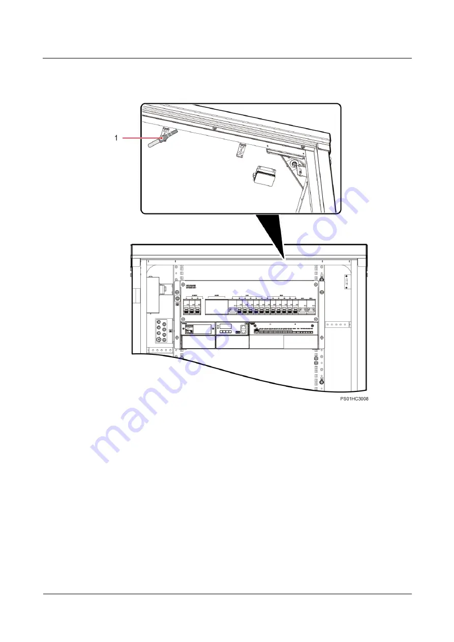
Figure 4-32


Position of the temperature sensor in the equipment compartment (for the 

TP48200A-HT19C1 & HT19C2) 


(1) Temperature sensor for the equipment compartment 


Step 4


Properly place the new temperature sensor in the equipment compartment and bind it securely 
with a cable tie. 

Step 5


Reconnect the temperature sensor cable to the UIM. 

Step 6


Disconnect the ground cable from the ESD wrist strap, and take off the ESD wrist strap and 
ESD gloves. 

----End 

Содержание Telecom Power TP48200A-DT19C1

Страница 1: ...TP48200A DT19C1 TP48200A DT19C2 TP48200A HT19C1 and TP48200A HT19C2 Telecom Power User Manual Issue 03 Date 2019 11 15 HUAWEI TECHNOLOGIES CO LTD ...

Страница 2: ...tomer All or part of the products services and features described in this document may not be within the purchase scope or the usage scope Unless otherwise specified in the contract all statements information and recommendations in this document are provided AS IS without warranties guarantees or representations of any kind either express or implied The information in this document is subject to c...

Страница 3: ...fined as follows Symbol Description Indicates a hazard with a high level of risk which if not avoided will result in death or serious injury Indicates a hazard with a medium level of risk which if not avoided could result in death or serious injury Indicates a hazard with a low level of risk which if not avoided could result in minor or moderate injury Indicates a potentially hazardous situation w...

Страница 4: ...o Ltd iii Change History Changes between document issues are cumulative The latest document issue contains all the changes made in earlier issues Issue 03 2019 11 15 Deleted contents about the app Optimized the content about rectifiers Issue 02 2019 02 26 Optimized the content of the document Issue 01 2013 08 01 This issue is the first official release ...

Страница 5: ...11 2 Overview 15 2 1 Introduction 15 2 2 Model Number Description 16 2 3 System Features 16 2 4 Working Principles 17 2 5 Configurations 17 3 Components 20 3 1 Interior 20 3 2 PDU 26 3 2 1 Battery Switch 27 3 3 Rectifier 27 3 4 SMU02B 29 3 5 UIM02C 32 3 6 Temperature Control Unit for the TP48200A DC1 and TP48200A DC2 35 3 6 1 Direct Ventilation 35 3 6 2 TEC 36 3 7 Temperature Control Unit for the ...

Страница 6: ...r Volt 53 4 2 5 DC Under Volt 54 4 2 6 Batt Chg Overcur 54 4 2 7 LLVD Disconnected 55 4 2 8 BLVD Disconnected 55 4 2 9 Batt Loop Trip 55 4 2 10 High Amb Temp 56 4 2 11 Low Amb Temp 56 4 2 12 High Amb Humi 56 4 2 13 Low Ambient Humidity 57 4 2 14 Batt High Temp 57 4 2 15 Batt Low Temp 58 4 2 16 Door Alarm 58 4 2 17 Water Alarm 58 4 2 18 Smoke Alarm 59 4 2 19 Rect Fault 59 4 2 20 Rect Protection 59 ...

Страница 7: ...eplacing an Ambient Temperature and Humidity Sensor 85 4 4 13 Replacing a Smoke Sensor 86 4 4 14 Replacing a Battery Temperature Sensor 88 4 4 15 Replacing a Temperature Sensor for the Equipment Compartment 89 4 4 16 Replacing a Water Sensor 92 A Technical Specifications 94 A 1 Environmental Specifications 94 A 2 Electrical Specifications 94 A 3 EMC Specifications 96 A 4 Cabinet Specifications 96 ...

Страница 8: ... injuries or property damage are not covered under the warranty Follow local laws and regulations when installing operating or maintaining the equipment The safety instructions in this document are only supplements to local laws and regulations Huawei will not be liable for any consequences of the following circumstances Operation beyond the conditions specified in this document Installation or us...

Страница 9: ...elmet and shoes as shown in the following figure Use insulated tools or tools with insulated handles as shown in the following figure Follow the specified procedures for installation operation and maintenance Ensure that bolts are tightened with a torque wrench and marked using red or blue color Installation personnel mark tightened bolts in blue Quality inspection personnel confirm if the bolts a...

Страница 10: ...r installing the equipment remove idle packing materials such as cartons foam plastics and cable ties from the equipment area In the case of a fire immediately leave the building or the equipment area and turn on the fire alarm bell or make an emergency call Do not enter the building on fire in any case Do not stop using protective devices Pay attention to the warnings cautions and related precaut...

Страница 11: ...rminal Indicates equipotential bonding This symbol is found with equipotential terminals inside equipment Indicates electrostatic discharge ESD This symbol is used in all electrostatic sensitive areas Before operating equipment in these areas wear ESD gloves or an ESD wrist strap Indicates that the equipment is safe to use at altitudes below 2000 m 6561 6 ft Indicates that the equipment is not saf...

Страница 12: ...pecial equipment Professionals personnel who are trained or experienced in equipment operations and are clear of the sources and degree of various potential hazards in equipment installation operation and maintenance Trained personnel personnel who are technically trained have required experience are aware of possible hazards on themselves in certain operations and are able to take protective meas...

Страница 13: ...ct Before connecting the power supply ensure that cable connections are correct If the equipment has multiple inputs disconnect all the inputs before operating the equipment Cabling When routing cables ensure that a distance of at least 30 mm exists between the cables and heat generating components or areas This prevents damage to the insulation layer of the cables Do not route cables behind the a...

Страница 14: ...ensure that the cabinet is secured and will not tilt or fall down due to loss of balance which can cause personal injury or equipment damage Do not expose the equipment to flammable or explosive gas or smoke Do not perform any operation on the equipment in such environments Installation at Heights Working at heights refers to operations that are performed at least 2 meters above the ground Do not ...

Страница 15: ... at heights Do not allow people to stay or pass under the area involving working at heights Inspect the scaffolding springboards and workbenches used for working at heights in advance to ensure that their structures are solid and not overloaded Dismantle the scaffolding from top down after finishing the job Do not dismantle the upper and lower layers at the same time When removing a part ensure th...

Страница 16: ...sed ensure that the pull ropes are secured and the ladder is held firm Before using a ladder check that it is intact and confirm its load bearing capacity Do not overload it Ensure that the wider end of the ladder is at the bottom or protective measures have been taken at the bottom to prevent the ladder from sliding Ensure that the ladder is securely positioned The recommended angle for a ladder ...

Страница 17: ...ladder Drilling Holes When drilling holes into a wall or floor observe the following safety precautions Do not drill holes into the equipment Doing so may affect the electromagnetic shielding of the equipment and damage components or cables inside Metal shavings from drilling may short circuit boards inside the equipment Wear goggles and protective gloves when drilling holes When drilling holes pr...

Страница 18: ...assemble alter or damage batteries for example insert sundries into batteries or immerse batteries in water or other liquids When replacing a battery use a battery of the same model or type Improper replacement may cause the battery to explode Do not connect a metal conductor to the battery poles or touch the battery terminals Otherwise the battery may be short circuited and heat up which can caus...

Страница 19: ...batteries horizontally Note the polarities when installing batteries Do not short circuit the positive and negative poles of the same battery or battery string Otherwise the battery may be short circuited When installing a battery string retain at least one breakpoint to prevent a loop being formed After checking that the installation is correct close the breakpoints to finish the installation Dur...

Страница 20: ...ing or handling a battery whose electrolyte leaks note that the leaking electrolyte may hurt human bodies If the electrolyte overflows follow the instructions of the battery manufacturer or neutralize the electrolyte by using sodium bicarbonate NaHCO3 or sodium carbonate Na2CO3 Lithium Battery The safety precautions for lithium batteries are similar to those for lead acid batteries except that you...

Страница 21: ...2 TP48200A HT19C1 and TP48200A HT19C2 Telecom Power User Manual 1 Safety Precautions Issue 03 2019 11 15 Copyright Huawei Technologies Co Ltd 14 When maintenance is complete return the waste lithium battery to the maintenance office ...

Страница 22: ...ologies Co Ltd 15 2 Overview 2 1 Introduction The TP48200A DT19C1 TP48200A DT19C2 TP48200A HT19C1 and TP48200A HT19C2 are integration communications power systems that supply power to and back up power for 48 V DC outdoor communications equipment The appearances of the four cabinets are similar as shown in Figure 2 1 Figure 2 1 Cabinet appearance ...

Страница 23: ...tage range of 85 V AC to 300 V AC Comprehensive battery management Comprehensive AC and DC surge protection design Network application over a fast Ethernet FE port and an RS485 RS232 port Communication with Huawei NetEco or third party network management systems NMSs over protocols such as the Simple Network Management Protocol SNMP and Hypertext Transfer Protocol Secure HTTPS to enable remote man...

Страница 24: ...nd charge batteries When the AC power is absent rectifiers stop working and batteries start to power loads After the AC power resumes rectifiers power DC loads and charge batteries again The SMU monitors the operating status of each component in the power system in real time and performs appropriate intelligent control When detecting a fault the SMU generates an alarm The SMU monitors and regulate...

Страница 25: ...eaker One 2 pole 100 A circuit breaker Optional AC output circuit breaker One 2 pole 10 A circuit breaker and one 3 pole maintenance socket protected by an 10 A electric residual current device RCD DC output Battery low voltage disconnection BLVD two 1 pole 10 A circuit breakers and four 1 pole 16 A circuit breakers Load low voltage disconnection LLVD one 1 pole 100 A circuit breaker one 1 pole 63...

Страница 26: ... environments with simple shielding measures where humidity can reach 100 Class C environments refer to sea environments or outdoor land environments with simple shielding measures near pollution sources If a site is near a pollution source it is at most 3 7 km away from salt water such as the sea and salt lakes 3 km away from heavy pollution sources such as smelteries coal mines and thermal power...

Страница 27: ...T19C2 TP48200A HT19C1 and TP48200A HT19C2 Telecom Power User Manual 3 Components Issue 03 2019 11 15 Copyright Huawei Technologies Co Ltd 20 3 Components 3 1 Interior TP48200A DT19C1 Figure 3 1 shows the TP48200A DT19C1 interior ...

Страница 28: ...intenance socket 3 Air filter 4 Optional Electric door lock 5 Optional Bluetooth controller 6 TCUA control box 7 Thermoelectric cooler TEC 8 Space for installing batteries 9 Space for installing customer equipment 10 Space for installing rectifiers 11 User interface module UIM 12 DC power distribution unit PDU 13 Site monitoring unit SMU 14 AC input circuit breaker 15 Fan assembly 16 Battery switc...

Страница 29: ...TP48200A DT19C2 interior Figure 3 2 TP48200A DT19C2 interior 1 Optional Intelligent electric meter 2 Optional Maintenance socket 3 Air filter 4 Optional Electric door lock 5 Optional Bluetooth controller 6 TCUA control box 7 TEC 8 Space for installing batteries 9 Space for installing customer equipment 10 Space for installing rectifiers 11 UIM 12 DC PDU 13 SMU 14 AC input circuit breaker 15 Fan as...

Страница 30: ...es Co Ltd 23 16 Battery switch 17 Cabinet ground bar 18 Optional Current transformer TP48200A HT19C1 Figure 3 3 shows the TP48200A HT19C1 interior Figure 3 3 TP48200A HT19C1 interior 1 Optional Intelligent electric meter 2 Optional Maintenance socket 3 Heat exchanger HXC70S 4 Optional Bluetooth controller 5 Optional Electric door lock 6 TCUA control box ...

Страница 31: ...ght Huawei Technologies Co Ltd 24 7 TEC 8 Space for installing batteries 9 Space for installing customer equipment 10 Space for installing rectifiers 11 UIM 12 SMU 13 DC PDU 14 AC input circuit breaker 15 Battery switch 16 Cabinet ground bar 17 Optional Current transformer TP48200A HT19C2 Figure 3 4 shows the TP48200A HT19C2 interior ...

Страница 32: ...tional Intelligent electric meter 2 Optional Maintenance socket 3 Heat exchanger HXC70S 4 Optional Bluetooth controller 5 Optional Electric door lock 6 TCUA control box 7 TEC 8 Space for installing batteries 9 Space for installing customer equipment 10 Space for installing rectifiers 11 UIM 12 SMU 13 DC PDU 14 AC input circuit breaker 15 Battery switch 16 Cabinet ground bar 17 Optional Current tra...

Страница 33: ...200A HT19C1 Figure 3 5 PDU for the TP48200A DT19C1 and TP48200A HT19C1 1 AC input circuit breakers 2 AC surge protective device SPD 3 LLVD circuit breakers 4 BLVD circuit breakers 5 Battery circuit breakers The TCUA control box occupies the F10 BLVD circuit breaker TP48200A DT19C2 and TP48200A HT19C2 Figure 3 6 shows the PDU for the TP48200A DT19C2 and TP48200A HT19C2 Figure 3 6 PDU for the TP4820...

Страница 34: ...D circuit breaker 3 2 1 Battery Switch Figure 3 7 Battery switch 1 Battery switch behind the cover The battery switch is in the AUTO position by default before delivery and the system is under automatic control Open the cover and flip the battery switch to MANUAL only when you need to connect battery power supply manually Remember to flip the battery switch back to AUTO after the commissioning 3 3...

Страница 35: ...fier is being queried Blinking at 4 Hz The rectifier is loading an application program Alarm indicator Yellow Off No alarm has been generated Steady on The rectifier has generated an alarm due to ambient overtemperature The rectifier has generated an alarm for shutdown due to ambient overtemperature or undertemperature The rectifier is protecting itself against AC input overvoltage or undervoltage...

Страница 36: ...hernet FE port 10 LCD Indicators Table 3 2 Indicator description Name Color Status Description Run indicator Green Off The SMU is faulty or has no DC input Blinking slowly 0 5 Hz The SMU is running properly and communicating with the host properly Blinking fast 4 Hz The SMU is running properly but fails to communicate with the host properly Minor alarm indicator Yellow Off No minor or warning alar...

Страница 37: ...sed within 30 seconds You need to log in again if no button is pressed within 1 minute To increase or decrease a parameter value quickly hold down or To restart the SMU hold down and for 10 seconds To increase or decrease the LCD contrast ratio hold down and or for 2 seconds USB Ports You can quickly deploy a site import and export configuration files export running logs and upgrade software by in...

Страница 38: ...o protocol SNMP and TCP Modbus protocol RS485 RS232 Baud rate 1200bit s 2400bit s 4800bit s 9600bit s 14400bit s 19200bit s 115200bit s Master slave protocol YDN protocol and Modbus protocol NOTE All these ports are protected by a security mechanism Figure 3 10 FE RS485 RS232 port pins Table 3 5 Pin definitions for the FE port Pin Signal Description 1 TX Transmits data over FE 2 TX 3 RX Receives d...

Страница 39: ...orts eight dry contact outputs six dry contact inputs and seven sensor ports including one ambient temperature and humidity input one water sensor input two ambient temperature inputs one door status sensor input one smoke sensor input and one battery temperature input Figure 3 11 UIM02C panel Ports Table 3 7 UIM02C ports Port Type Silk Screen Description Sensor ports TEM HUM Ambient temperature a...

Страница 40: ...ry contact output ports ALM1 NOTE For the associations between the dry contact output ports and alarms see the appendix ALM2 ALM3 ALM4 ALM5 ALM6 ALM7 ALM8 Communications port COM RS485 port Communication Port Table 3 8 COM communication port description Communication Port Communications Parameter Communications Protocol Function COM port Baud rate 9600 bit s 19 200 bit s 115 200 bit s M S and Modb...

Страница 41: ...hnologies Co Ltd 34 Figure 3 12 Pins in the COM port Table 3 9 Pin definitions for the COM port Pin Signal Description 1 RX Receives data over RS485 2 RX 4 TX Sends data over RS485 5 TX 6 PGND Connects to the ground 3 7 8 None N A Pins Figure 3 13 shows the pin numbers of the sensor ports Table 3 10 defines the pins Figure 3 13 UIM02C pin numbers ...

Страница 42: ...ture Control Unit for the TP48200A DC1 and TP48200A DC2 The equipment compartments of the TP48200A DT19C1 and TP48200A DT19C2 use direct ventilation for air cooling while the battery compartments use a TEC The direct ventilation unit consists of a fan assembly controlled by a UIM02C The TEC consists of a TEC module and a TCUA control box The TCUA control box controls the operating of the TEC modul...

Страница 43: ...nents Issue 03 2019 11 15 Copyright Huawei Technologies Co Ltd 36 Figure 3 14 Airflow direction in the direct ventilation unit 3 6 2 TEC The TEC unit consists of the TEC module TEC04C and TCUA control box It controls temperatures for the battery compartment TEC Module TEC04C Figure 3 15 shows a TEC04C ...

Страница 44: ...i Technologies Co Ltd 37 Figure 3 15 TEC04C 1 External circulation fan 2 External circulation heat sink 3 Semiconductor refrigeration chip 4 Internal circulation heat sink 5 Internal circulation fan TCUA TCUA controls the operating of the fans and refrigeration chip monitors the TEC and reports alarms if faults occur Figure 3 16 shows a TCUA ...

Страница 45: ...ation fan port 2 14 Temperature signal port 2 TEC Working Principle The TEC cools and heats air through internal and external circulation Table 3 11 describes how the TEC works Figure 3 17 shows the TEC airflow directions Table 3 11 TEC working principles Function Working Principle Cooling The TCUA control box controls the refrigeration chip in the TEC module to cool the internal circulating air T...

Страница 46: ...rculation heat sink The internal circulation heat sink heats the air and then returns the heated air to the battery compartment through the air exhaust vents Meantime the external circulation fan operates according to control logic and draws natural air into the external circulation heat sink The air gives out heat and returns to the external environment through the air exhaust vents on the extern...

Страница 47: ...through the heat exchanging core from top to bottom then releases heat to change to cold air and finally returns to the equipment compartment through the internal air exhaust vent under the heat exchanger External circulation Natural air is drawn by the external circulation fan under the heat exchanger into the heat exchanger from the outside of the cabinet passes through the heat exchanging core ...

Страница 48: ... Copyright Huawei Technologies Co Ltd 41 3 8 Sensor Figure 3 19 shows the positions of all sensors in the TP48200A DT19C1 DT19C2 while Figure 3 20 shows those for the TP48200A HT19C1 HT19C2 Figure 3 19 Sensors TP48200A DT19C1 DT19C2 1 Optional Ambient temperature and humidity sensor 2 Door status sensor 3 Optional Smoke sensor ...

Страница 49: ...s Co Ltd 42 4 Temperature sensor in the equipment compartment 5 Battery temperature sensor 6 Optional Water sensor Figure 3 20 Sensors TP48200A HT19C1 HT19C2 1 Optional Ambient temperature and humidity sensor 2 Door status sensor 3 Temperature sensor in the equipment compartment 4 Optional Smoke sensor 5 Battery temperature sensor 6 Optional Water sensor ...

Страница 50: ...TP48200A HT19C2 Telecom Power User Manual 3 Components Issue 03 2019 11 15 Copyright Huawei Technologies Co Ltd 43 3 8 1 Smoke Sensor Figure 3 21 Smoke sensor 1 1 Wiring port 2 Base 3 Indicator Figure 3 22 Smoke sensor 2 1 Wiring port 2 Base 3 Indicator ...

Страница 51: ... and TP48200A HT19C2 Telecom Power User Manual 3 Components Issue 03 2019 11 15 Copyright Huawei Technologies Co Ltd 44 3 8 2 Temperature and Humidity Sensor Figure 3 23 Temperature and humidity sensor 1 Figure 3 24 Temperature and humidity sensor 2 ...

Страница 52: ...ure 3 26 Battery temperature sensor 3 8 5 Temperature Sensor in the Equipment Compartment Figure 3 26 shows the temperature sensor in the equipment compartment 3 9 Optional Intelligent Electric Meter An intelligent electric meter works together with a current transformer and can measure the AC current voltage frequency power factor active power and total power and facilitates automatic management ...

Страница 53: ... 2019 11 15 Copyright Huawei Technologies Co Ltd 46 Appearance and Pin Definitions Figure 3 27 Appearance of the current transformer Figure 3 28 Appearance and pins of the intelligent electric meter Table 3 12 Pin definitions of the intelligent electric meter Pin Definitions 1 2 Power supply 3 4 RS485 communication ...

Страница 54: ...ns 5 Phase A voltage 6 Phase B voltage 7 Phase C voltage 8 Neutral wire 10 Current transformer port 3 10 Optional Bluetooth Door Lock The Bluetooth door lock consists of the electric door lock and Bluetooth controller which is used to control the electric door lock 3 10 1 Optional Electric Door Lock Appearance Figure 3 29 shows an electric door lock Figure 3 29 Electric door lock ...

Страница 55: ...nologies Co Ltd 48 Port Definitions Figure 3 30 Ports on the electric door lock Table 3 13 Port definitions of the electric door lock Pin Definitions Description 1 TX Sends data over RS485 2 TX 3 12 V Supplies power for the electric door lock 4 RX Receives data over RS485 5 RX 6 OPEN_DOOR Controls the electric door lock reserved 7 GND GND 8 GND GND ...

Страница 56: ...48200A HT19C2 Telecom Power User Manual 3 Components Issue 03 2019 11 15 Copyright Huawei Technologies Co Ltd 49 3 10 2 Optional Bluetooth Controller Appearance Figure 3 31 Bluetooth controller Port Definitions Figure 3 32 Ports on the Bluetooth controller ...

Страница 57: ...al 3 Components Issue 03 2019 11 15 Copyright Huawei Technologies Co Ltd 50 Table 3 14 Port definitions of the Bluetooth controller Pin Definitions 1 AC input 2 AC input 3 Connects to pin 4 4 Connects to pin 3 5 12 V 6 12 V 7 Controls the electric door lock 8 Controls the electric door lock 9 ...

Страница 58: ...e door lock Fan Dust accumulates on the fan surface By observing Thick dust accumulates on the fan surface Clean up the dust from the fan The fan surface is intact and the rotational speed noise and vibration is in the normal range By observing and listening to the fans The fan is damaged the noise is too loud or the vibration is abnormal Replace the fan Heat exchanger Dust accumulates on the surf...

Страница 59: ...ust accumulates on the air filter Replace the air filter Electrical specifications The output voltage is normal Multimeter The battery circuit voltage or load circuit voltage exceeds its threshold For details see 4 2 Rectifying Common Faults Preventive maintenance inspection PMI Indicators are normal By observing An alarm is generated Appearance The paint or electroplated coating on the cabinet fl...

Страница 60: ...ault 4 2 2 AC Over Volt Possible Causes The AC overvoltage alarm threshold is incorrectly set on the SMU The power grid is faulty Measures 1 Check whether the AC overvoltage alarm threshold is correctly set If not set the threshold to the correct value 2 Check whether the AC input voltage exceeds the AC overvoltage alarm threshold 280 V AC by default If so handle the AC input fault 4 2 3 AC Under ...

Страница 61: ...er system voltage has been manually set to a very low value Rectifiers are faulty Measures 1 Check whether an AC power failure has occurred If so rectify the fault to restore the AC power supply 2 Check whether the DC undervoltage alarm threshold 45 V DC by default is correctly set If not set the threshold to the correct value 3 Check whether the load current is greater than the present power syst...

Страница 62: ... Possible Causes An AC power failure has occurred Batteries are manually disconnected The battery disconnection voltage has been set to a very high value on the SMU Measures 1 Check whether an AC power failure has occurred If so rectify the fault to restore the AC power supply 2 Check whether batteries are manually disconnected If so check with other maintenance personnel whether the batteries can...

Страница 63: ...If yes rectify the fault The alarm is cleared when the cabinet temperature falls within the allowed range 3 Check whether the ambient temperature sensor is faulty If yes replace the temperature sensor 4 2 11 Low Amb Temp This alarm is generated only for the power system that has an ambient temperature sensor installed Possible Causes The low ambient temperature alarm threshold is incorrectly set T...

Страница 64: ...The humidity is too low in the cabinet where the humidity sensor is located The humidity sensor is faulty Measures 1 Check whether the low humidity alarm threshold 10 RH by default is correctly set If no adjust it to a proper value 2 Check whether the humidity inside the cabinet is too low If yes adjust the humidity The alarm is cleared when the humidity returns to the allowed range 3 Check whethe...

Страница 65: ...ault is correctly set If not set the threshold to the correct value 2 Check whether the temperature control system for the battery compartment is faulty If so rectify the fault The alarm is cleared when the temperature in the battery compartment becomes normal 3 Check whether the battery temperature sensor is faulty If so replace the battery temperature sensor 4 2 16 Door Alarm This alarm is gener...

Страница 66: ...m and clear the alarm on the SMU 2 Check whether the smoke sensor is faulty If the smoke sensor is faulty replace it 4 2 19 Rect Fault Possible Causes Rectifier connections are loose A rectifier is faulty Measures 1 Check the Fault indicator on the rectifier panel If it is steady red remove the rectifier and then reinstall it after the indicator turns off 2 If the alarm persists replace the rectif...

Страница 67: ...osition remove the rectifier and reinstall it 3 If the alarm persists replace the rectifier 4 2 22 Load Loop Break Possible Causes The load circuit breaker has tripped or the load fuse has blown The load circuit breaker or the fuse detection cable is disconnected Measures 1 Check whether the load circuit breaker has tripped or the load fuse has blown If so locate and rectify the circuit fault and ...

Страница 68: ...ircuit breaker is OFF 4 3 3 Identifying Rectifier Faults A rectifier is damaged if any of the following conditions is not met When the rectifier does not communicate with the SMU and the AC input voltage is around 220 V the green indicator on the rectifier is steady on and the other indicators are off The rectifier output is normal The SMU can perform equalized charging float charging and current ...

Страница 69: ...ON position and do not turn off the battery switch and the AC input switch at the same time Obtain prior written consent from the customer if load disconnection is required Do not perform maintenance on rainy days Otherwise rain water can enter the system and damage devices and components 4 4 1 Replacing a Rectifier Prerequisites Protective gloves and the cabinet door key are available The new rec...

Страница 70: ...ce the new rectifier at the entry of the correct slot Step 6 Gently slide the rectifier into the slot along the guide rails until it is engaged Close the handle and push the locking latch towards the right to lock the handle as shown in Figure 4 2 Figure 4 2 Installing a rectifier Step 7 Remove the protective gloves End Follow up Procedure Pack the removed component and send it to the local Huawei...

Страница 71: ...subrack push the locking latch towards the left and pull out the handle Step 4 Slide the SMU into the subrack slowly along the guide rails push in the handle and then push the locking latch towards the right Step 5 Reset the parameters on the SMU Figure 4 4 Installing an SMU End Follow up Procedure Pack the removed component and send it to the local Huawei warehouse 4 4 3 Replacing an AC SPD Prere...

Страница 72: ...p 2 Push down on the faulty AC SPD and pull it out as shown in Figure 4 5 Step 3 Install the new AC SPD as shown in Figure 4 5 Figure 4 5 Replacing an AC SPD Step 4 Disconnect the ground cable for the ESD wrist strap and remove the ESD wrist strap and gloves End Follow up Procedure Check that the alarm for the AC SPD is cleared 4 4 4 Replacing a Circuit Breaker Prerequisites Before replacing an AC...

Страница 73: ... circuit breaker using a Phillips screwdriver and open the buckle at the base of the circuit breaker using an insulated flat head screwdriver Step 5 Remove the circuit breaker from the guide rail Figure 4 6 shows how to remove the circuit breaker Figure 4 6 Removing the circuit breaker Step 6 Switch off the new circuit breaker Press the buckle at the circuit breaker base using an insulated flat he...

Страница 74: ... alarm has disappeared 4 4 5 Replacing the PCB of UIM02C Prerequisites An ESD wrist strap ESD gloves ESD box or bag cabinet door key and required tools are available The new PCB of UIM02C is intact Procedure Step 1 Connect the ground cable to the ESD wrist strap and wear the ESD wrist strap and ESD gloves Step 2 Record the positions on the UIM02C panel for connecting signal cables and disconnect t...

Страница 75: ...ght Huawei Technologies Co Ltd 68 Figure 4 8 Taking out the main board of UIM02C Step 4 Remove the 48 V power cable from the PCB of UIM02C Figure 4 9 Removing the 48 V power cable Step 5 Record the positions where the PCB of UIM02C connects to all the cables and then disconnect the cables Step 6 Remove the PCB as shown in Figure 4 10 ...

Страница 76: ...cable from the ESD wrist strap and remove the ESD wrist strap and ESD gloves End Follow up Procedure Pack the removed component and return it to the local Huawei warehouse 4 4 6 Replacing the Internal Circulation Fan of the Heat Exchanger for the TP48200A HC1 HC2 Prerequisites Prepare an ESD wrist strap a pair of ESD gloves an ESD box or bag the cabinet door key and a maintenance tool kit Check th...

Страница 77: ...3 Removing the internal circulation fan 1 Record the position where cables connect to the internal circulation fan and then disconnect the cables 2 Remove the cover from the internal circulation fan as shown in Figure 4 11 Figure 4 11 Removing the cover from the internal circulation fan 3 Remove the fan fixing plate from the internal circulation fan as shown in Figure 4 12 ...

Страница 78: ...12 Removing the fixing plate from the internal circulation fan 4 Remove the internal circulation fan as shown in Figure 4 13 Figure 4 13 Removing the internal circulation fan Step 4 Install a new internal circulation fan 1 Secure the internal circulation fan to the fan fixing plate using screws 2 Install the fan fixing plate 3 Install the cover for the internal circulation fan ...

Страница 79: ... Prerequisites Prepare an ESD wrist strap a pair of ESD gloves an ESD box or bag the cabinet door key and a maintenance tool kit Check that the new fan is intact Context You only need to disconnect the power supply to the TCUA control box but do not need to disconnect the AC input to the power system Procedure Step 1 Connect the ground cable to the ESD wrist strap and put on the ESD wrist strap an...

Страница 80: ...A HT19C2 Telecom Power User Manual 4 Maintenance Issue 03 2019 11 15 Copyright Huawei Technologies Co Ltd 73 Figure 4 14 Removing the cover from the external circulation fan 3 Remove the fan fixing plate from the external circulation fan as shown in Figure 4 15 ...

Страница 81: ...intenance Issue 03 2019 11 15 Copyright Huawei Technologies Co Ltd 74 Figure 4 15 Removing the fixing plate from the external circulation fan 4 Remove the external circulation fan as shown in Figure 4 16 Figure 4 16 Removing the external circulation fan Step 4 Install a new external circulation fan ...

Страница 82: ...isites Prepare an ESD wrist strap a pair of ESD gloves an ESD box or bag the cabinet door key and a maintenance tool kit Check that the new fan is intact Context You only need to disconnect the power cable from the fan but do not need to disconnect the AC input Procedure Step 1 Connect the ground cable to the ESD wrist strap and put on the ESD wrist strap and ESD gloves Step 2 Disconnect the power...

Страница 83: ...ue 03 2019 11 15 Copyright Huawei Technologies Co Ltd 76 Figure 4 17 Taking out the fan assembly Step 4 Remove the fan 1 Unscrew and remove the cover from the fan assembly 2 Unscrew the fan fixing plate and remove the plate from the fan as shown in Figure 4 18 3 Unscrew and remove the fan as shown in Figure 4 19 ...

Страница 84: ...T19C1 and TP48200A HT19C2 Telecom Power User Manual 4 Maintenance Issue 03 2019 11 15 Copyright Huawei Technologies Co Ltd 77 Figure 4 18 Removing the cover and fan fixing plate from the fan Figure 4 19 Removing the fan Step 5 Install a new fan ...

Страница 85: ...ble to the UIM02C panel based on the recorded position Step 8 Disconnect the ground cable from the ESD wrist strap and take off the ESD wrist strap and ESD gloves End 4 4 9 Replacing a TCUA Control Board Prerequisites You have obtained an ESD wrist strap a pair of ESD gloves an ESD box or bag and the cabinet door key The new TCUA control board is intact Context You only need to disconnect the powe...

Страница 86: ...d TP48200A HT19C2 Telecom Power User Manual 4 Maintenance Issue 03 2019 11 15 Copyright Huawei Technologies Co Ltd 79 Figure 4 20 Removing a TCUA control box Step 3 Remove the TCUA control board 1 Unscrew the TCUA control board as shown in Figure 4 21 ...

Страница 87: ...the appendix Step 4 Install a new TCUA control board 1 Set the jumper caps for the new TCUA control board based on the recorded information 2 Install the new TCUA control board into the control box 3 Connect the cable between the TCUA module and the new TCUA control board based on the recorded information Step 5 Install the TCUA control box 1 Tighten the screws to secure the TCUA control box 2 Con...

Страница 88: ...he power system Procedure Step 1 Connect the ground cable to the ESD wrist strap and put on the ESD wrist strap and ESD gloves Step 2 Remove the TEC control box 1 Switch off the circuit breaker F10 for the TCUA control box on the DC PDU 2 Record positions where cables connect to the TCUA control box and disconnect the cables 3 Unscrew and remove the TCUA control box as shown in Figure 4 20 Step 3 ...

Страница 89: ...1 TP48200A DT19C2 TP48200A HT19C1 and TP48200A HT19C2 Telecom Power User Manual 4 Maintenance Issue 03 2019 11 15 Copyright Huawei Technologies Co Ltd 82 Figure 4 22 Removing the external cover from the cabinet door ...

Страница 90: ...ten the screws 3 Connect the cables between the TEC and the TCUA control board based on the recorded positions Step 5 Install the TCUA control box 1 Properly place the TCUA control box and tighten the screws 2 Connect the signal cable to the TCUA control box based on the recorded position 3 Switch on the circuit breaker F10 for the TCUA control box on the DC PDU Step 6 Disconnect the ground cable ...

Страница 91: ...lace the air filter directly and do not need to disconnect the AC input Procedure Step 1 Connect the ground cable to the ESD wrist strap and put on the ESD wrist strap and ESD gloves Step 2 Loosen the screws and then remove the air filter Figure 4 24 Removing the air filter Step 3 Properly place the new air filter place the side with label on the up direction and place the side with tapes towards ...

Страница 92: ...new ambient temperature and humidity sensor is intact Procedure Step 1 Connect the ground cable to the ESD wrist strap and put on the ESD wrist strap and ESD gloves Step 2 Remove the ambient temperature and humidity sensor cable from the UIM as shown in Figure 4 25 Figure 4 25 Removing the temperature and humidity sensor cable Step 3 Remove the temperature and humidity sensor as shown in Figure 4 ...

Страница 93: ...e it to the base Step 5 Reconnect the ambient temperature and humidity sensor cable to the UIM Step 6 Disconnect the ground cable from the ESD wrist strap and take off the ESD wrist strap and ESD gloves End 4 4 13 Replacing a Smoke Sensor Prerequisites An ESD wrist strap ESD gloves ESD box or bag cabinet door key and required tools are available The new smoke sensor is intact Procedure Step 1 Conn...

Страница 94: ...ors and both can be replaced in the same manner Figure 4 27 Removing the smoke sensor Step 3 Install the new smoke sensor 1 Place the smoke sensor base correctly and tighten the screws for it 2 Place the new smoke sensor correctly and press and push it in the CLOSE direction 3 Reconnect the removed cables to the smoke sensor Step 4 Disconnect the ground cable of the ESD wrist strap and remove the ...

Страница 95: ...x or bag the cabinet door key and a maintenance tool kit The new battery temperature sensor is intact Procedure Step 1 Connect the ground cable to the ESD wrist strap and put on the ESD wrist strap and ESD gloves Step 2 Remove the battery temperature sensor cable from the UIM as shown in Figure 4 28 Figure 4 28 Removing the battery temperature sensor cable Step 3 Cut off the cable tie of the batte...

Страница 96: ...UIM Step 6 Disconnect the ground cable from the ESD wrist strap and take off the ESD wrist strap and ESD gloves End 4 4 15 Replacing a Temperature Sensor for the Equipment Compartment Prerequisites Prepare an ESD wrist strap a pair of ESD gloves an ESD box or bag the cabinet door key and a maintenance tool kit Check that the new temperature sensor is intact Procedure Step 1 Connect the ground cabl...

Страница 97: ...pyright Huawei Technologies Co Ltd 90 Figure 4 30 Removing the temperature sensor cable Step 3 Cut off the cable tie of the sensor in the equipment compartment and remove it Figure 4 31 Position of the temperature sensor in the equipment compartment for the TP48200A DT19C1 DT19C2 1 Temperature sensor for the equipment compartment ...

Страница 98: ...ure sensor in the equipment compartment for the TP48200A HT19C1 HT19C2 1 Temperature sensor for the equipment compartment Step 4 Properly place the new temperature sensor in the equipment compartment and bind it securely with a cable tie Step 5 Reconnect the temperature sensor cable to the UIM Step 6 Disconnect the ground cable from the ESD wrist strap and take off the ESD wrist strap and ESD glov...

Страница 99: ...ned an ESD wrist strap a pair of ESD gloves an ESD box or bag the cabinet door key and tools The new water sensor is intact Procedure Step 1 Connect the ground cable to the ESD wrist strap and put on the ESD wrist strap and ESD gloves Step 2 Remove the water sensor cable from the UIM as shown in Figure 4 33 Figure 4 33 Removing the water sensor cable Step 3 Cut off the cable tie of the water senso...

Страница 100: ... Ltd 93 Figure 4 34 Position of the water sensor Step 4 Properly place the new water sensor and bind it securely with a cable tie ensure that the sensor is 5 mm to 10 mm away from the cabinet bottom Step 5 Reconnect the water sensor cable to the UIM Step 6 Disconnect the ground cable from the ESD wrist strap and take off the ESD wrist strap and ESD gloves End ...

Страница 101: ...ature 40 C to 70 C Operating humidity 5 95 RH Storage humidity 5 95 RH Altitude 0 4000 m When the altitude ranges from 2000 m to 4000 m the operating temperature decreases by 1 C for each additional 200 m Noise level Complies with GR487 Acoustic pressure level 65dBA 1 5 m A 2 Electrical Specifications Table A 2 Electrical specifications Item Specifications AC input AC input system TP48200A DT19C1 ...

Страница 102: ...ing 5 20 100 load percentage AC input protection AC input overvoltage protection threshold 300 V AC AC input overvoltage recovery threshold When the voltage is restored to 290 V AC the output resumes AC input undervoltage protection threshold 85 V AC AC input undervoltage recovery threshold When the voltage is restored to 90 V AC the output resumes DC output protection DC output overvoltage protec...

Страница 103: ... 8 kV Signal ports comply with IEC61000 4 2 criterion R Contact discharge 2 kV Electrical fast transient EFT IEC61000 4 4 criterion B AC power port 2 kV DC power port 2 kV Radiated susceptibility RS IEC61000 4 3 criterion A 10 V m Conducted susceptibility CS IEC6100 4 6 criterion A Power port 10 V signal port 3 V Surge immunity IEC61000 4 5 criterion B AC power port differential mode 2 kV 8 20 us ...

Страница 104: ...anger Specifications Table A 5 HXC70S heat exchanger specifications Item Specifications Maximum power consumption 68 W Typical power consumption 50 W Heat exchanging capacity 800 W 80 W K 10 C Input voltage 48 V DC Service life 10 years Operating temperature 40 C to 45 C Storage temperature 40 C to 70 C Alarm reporting Generates alarms over dry contacts Normal closed faulty open Altitude 4000 m Fa...

Страница 105: ...ifications Table A 7 TEC04C specifications Item Specifications Rated voltage 48 V DC Rated cooling capacity L32 L32 200 W Heating capacity 300 W Rated Cooling Power Consumption 300 W Operating environment 40 C to 40 C Relative humidity 5 95 RH Storage environment 40 C to 70 C complying with the ETS 300 019 1 1 Class 1 2 Altitude 4700 m Service life 10 years Mean time between failures MTBF 100 000 ...

Страница 106: ...193 mm x 110 mm x 90 mm Operating temperature 45 C to 85 C A 9 Intelligent Electric Meter Specifications Table A 9 Intelligent electric meter specifications Item Specifications Dimensions L x W x H 72 mm x 76 mm x 63 mm Database update 1s Voltage measurement range Line voltage 30 600 V AC Phase voltage 20 400 V AC Continuous overload voltage 800 V AC Current measurement range 200 mA to 100 A Singl...

Страница 107: ...s Issue 03 2019 11 15 Copyright Huawei Technologies Co Ltd 100 Item Specifications Electric energy precision 1 0 0 5 C 1 0 5 L Operating temperature 10 C to 50 C Storage temperature 25 C to 75 C Relative humidity 20 95 RH non condensing Power input 18 90 V DC Two options 85 265 V AC or 85 330 V DC Power consumption 2 W ...

Страница 108: ...3 2019 11 15 Copyright Huawei Technologies Co Ltd 101 B Electrical Conceptual Diagram Figure B 1 Electrical conceptual diagram of the TP48200A DT19C1 and TP48200A HT19C1 220 VAC single phase and 220 380 VAC three phase four wire Figure B 2 Electrical conceptual diagram of the TP48200A DT19C2 and TP48200A HT19C2 110 VAC dual live wire ...

Страница 109: ...input DIN1 Dry contact input 1 DIN2 Dry contact input 2 DIN3 Dry contact input 3 DIN4 Dry contact input 4 DIN5 Dry contact input 5 DIN6 TP48200A DT19C1 and TP48200A DT19C2 TEC Alarm TP48200A HT19C1 and TP48200A HT19C2 TCUA Alarm Dry contact output The default setting closed alarm open normal can be modified ALM1 Mains faults ALM2 DC overvoltage and undervoltage ALM3 Rectifier faults ALM4 AC surge ...

Страница 110: ...Technologies Co Ltd 103 D Jumper Caps on the TCUA Control Board When replacing the TCUA control board you can set the DIP switch for each temperature control equipment based on the following information Figure D 1 Jumper caps on the TCUA control board TP48200A DT19C1 and TP48200A DT19C2 Figure D 2 Jumper caps on the TCUA control board TP48200A HT19C1 and TP48200A HT19C2 ...

Страница 111: ...nection of TCUA Control Board Issue 03 2019 11 15 Copyright Huawei Technologies Co Ltd 104 E Cables Connection of TCUA Control Board Figure E 1 Cables Connection of TCUAControl Board TP48200A DT19C1 DT19C2 1 TEC refrigeration chip port 2 TEC internal circulation fan port 3 TEC external circulation fan port ...

Страница 112: ...ion port 6 TEC temperature sensor port Figure E 2 Cables Connection of TCUAControl Board TP48200A HT19C1 HT19C2 1 TEC refrigeration chip port 2 TEC internal circulation fan port 3 TEC external circulation fan port 4 Heat exchanger extra temperature sensor port 5 Power input port 6 Heat exchanger internal circulation fan port 7 Heat exchanger external circulation fan port 8 Communication port 9 TEC...

Страница 113: ...6 F Acronyms and Abbreviations B BLVD Battery low voltage disconnection BBU baseband unit E EMC Electromagnetic compatibility EMI Electromagnetic interference EMS Electromagnetic susceptibility ESD electrostatic discharge H HTTPS Hypertext Transfer Protocol Secure L LLVD Load low voltage disconnection I IEC International Electrotechnical Commission M MTBF Mean time between failures ...

Страница 114: ...Telecom Power User Manual F Acronyms and Abbreviations Issue 03 2019 11 15 Copyright Huawei Technologies Co Ltd 107 S SMU Site monitoring unit SNMP Simple Network Management Protocol SPD Surge protection device T TCU Temperature control unit U UIM User interface module ...

Отзывы: