
TP48120A-HD15A1 & TP48120A-HD15A2 &
TP48200A-HD15A1 & TP48200A-HD15A2
Installation Guide
A Associations between Alarms and the Dry Contacts on
the UIM
Issue 03 (2014-12-02)
Huawei Proprietary and Confidential
Copyright © Huawei Technologies Co., Ltd.
74
A
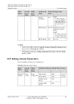
Associations between Alarms and the
Dry Contacts on the UIM
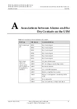
Table A-1
Associations between alarms and dry contacts
Port Type
Silk Screen
Associated Alarm
Dry Contact input
port
DIN1
Dry Contact input 1
DIN2
Dry Contact input 2
DIN3
Dry Contact input 3
DIN4
Dry Contact input 4
DIN5
Dry Contact input 5
DIN6
Dry Contact input 6
Dry Contact
output port
(closed: alarm;
open: normal) can
be modified by
customers.
ALM1
AC power failure alarm
ALM2
DC overvoltage or undervoltage alarm
ALM3
Rectifier fault alarm
ALM4
AC or DC SPD fault alarm
ALM5
Battery or load fuse blown alarm
ALM6
Battery overtemperature or undertemperature
alarm
ALM7
Door status alarm
ALM8
Fan, air conditioner, or heater fault alarm


