background image

Acceptance Manual  
Tecal RH2485 V2 Server 

Part II Operation Guide 


12 

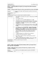
3. 

Select 

Steady On

 and click 

OK

4. 

Choose 

Temporary On

, enter a time period for illumination, such as 

10


seconds, and click 

OK

5. 

Select 

Off

 and click 

OK

. Observe the status of the location indicator on the 

server. 

Expected Result 

The indicator shows the three states properly and the selected state is the same as 
the actual state. 

Test Description 

When the location indicator is illuminated, it blinks blue at 1 Hz. 


T04-08  Setting the System Boot Option 

Objective 

To verify that you can set the system boot option on the iMana Web. 

Test Networking 
Diagram 

None 

Preset Conditions 

1. 

AC power is supplied to the server. 

2. 

The IP address of the iMana management network port is obtained. 

3. 

Internet Explorer 8.0 or Firefox 9.0 is installed on the terminal. 

4. 

JRE1.6u25 or later is installed on the terminal. 

5. 

The terminal is connected to the iMana network port of the server over the 
network. 

6. 

The CD-ROM drive is connected to the server. 

Test Procedures 

1. 

Log in to the iMana Web. 

2. 

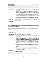
Choose 

Configuration

, click 

System Configuration

, and click 

System Boot 

Option

 on the right. 

3. 

Select 

CD-ROM Drive

 and click 

OK

4. 

Restart the server and check whether the setting takes effect. 

5. 

Select 

No override

 and click 

OK

6. 

Restart the server and check whether the setting takes effect. 

Expected Result 

1. 

The system boots from the CD-ROM drive. 

2. 

The system boots based on the BIOS settings. 

Test Description 


T05  Hard Disk Controller Functions 

T05-01  


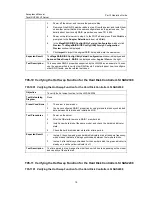
T05-0101   Configuring RAID 1 Properties by Using the Hard Disk Controller LSI SAS2308


Configuring RAID 1 Properties by Using the Hard Disk Controller 

LSI SAS2308

Содержание Tecal RH2485 V2

Страница 1: ...he Hard Disk Controller LSI2308 12 T05 02 Configuring RAID 1 Properties by Using the Hard Disk Controller LSI2208 13 T05 03 Configuring RAID 5 Properties by Using the Hard Disk Controller LSI2208 14 T05 04 Configuring RAID 10 Properties by Using the Hard Disk Controller LSI2208 15 T05 05 Configuring RAID 0 Properties by Using the Hard Disk Controller LSI2208 16 T05 06 Setting and Verifying a Globa...

Страница 2: ...ve To verify the server chassis structure Test Networking Diagram None Preset Conditions The structure of the mainboard hard disk backplane I O board indicator board VGA board and power board is proper Test Procedures 1 Check whether there are any scratches or oxidation on the chassis surface or deformation for the chassis cover 2 Check the mounting ears and the installation 3 Install the chassis ...

Страница 3: ...3 The PSUs are working properly and the indicators are steady green when the server is being powered on 4 No abnormal noise is heard during the power on operation Test Description None T01 0302 Verifying the Hot Swap Function Objective To verify that the PSUs are hot swappable Test Networking Diagram None Preset Conditions The structure of the mainboard hard disk backplane I O board indicator boar...

Страница 4: ...roperly during the test and no power failure occurs Test Description None T01 04 Hardware Detection T01 0401 Verifying Hardware Detection Objective To verify that the system detects hardware properly Test Networking Diagram None Preset Conditions The structure of the mainboard hard disk backplane I O board indicator board VGA board and power board is proper Test Procedures 1 Power on the server Pr...

Страница 5: ...the hard disk model and quantity Expected Result 1 The SETUP screen is displayed after you press Ctrl C 2 The LSI2308 BIOS version firmware versions and NVDATA version are displayed 3 The hard disk model and quantity are the same as actual configurations Test Description None T01 0502 Verifying the LSI2208 Hard Disk Controller Objective To verify that the hard disk controller operates properly Tes...

Страница 6: ... 100 24 3 The Internet Explorer 8 0 Firefox 9 0 or later is available Test Procedures 1 Power on the server system and wait about 20s 2 Observe the status of the indicator on the front panel 3 Connect the terminal to the iMana management network port connect to the Mgnt port on the left of the VGA port enter http 192 168 2 100 and press Enter 4 Log in with the user name root and password Huawei12 ...

Страница 7: ...ver 2 The default IP address of the iMana network port is 192 168 2 100 24 3 The Internet Explorer 8 0 Firefox 9 0 or later is available Test Procedures 1 Power on the server system and wait about 5 minutes until the BIOS setup phase is complete 2 Choose System Information System Hardware and view system hardware information 3 Choose Real time Monitoring Component and view the temperature monitori...

Страница 8: ...s 3 Run the free command and view the total memory capacity 4 Run the top command and press 1 View the number of the CPU kernels 5 Run the dmidecode grep i cpu command and view the CPU model 6 Run the lspci command and view the number of network interface cards NICs and host bus adapter HBA card information Expected Result 1 The OS is properly installed and the hard disks and the CD ROM drive are ...

Страница 9: ...e actual configurations 5 The HBA card information is the same as the actual configurations 6 The number and model of NICs are the same as the actual configurations Test Description None T04 iMana Functions T04 01 Verifying iMana Web Login Objective To verify that you can log in to the server iMana Web Test Networking Diagram None Preset Conditions 1 AC power is supplied to the server 2 The IP add...

Страница 10: ... corner 3 Check the active alarms displayed on the lower part of the page Expected Result 1 The icons show that the server has no alarm as shown in 2 No alarm is generated for the server Test Description T04 03 Querying Server Logs Objective To verify that you can query server logs on the iMana Web Test Networking Diagram None Preset Conditions 1 AC power is supplied to the server 2 The IP address...

Страница 11: ... To verify that you can power on power off and reset a server on the iMana Web Test Networking Diagram None Preset Conditions 1 AC power is supplied to the server 2 The IP address of the iMana management network port is obtained 3 Internet Explorer 8 0 or Firefox 9 0 is installed on the terminal 4 JRE1 6u25 or later is installed on the terminal 5 The terminal is connected to the iMana network port...

Страница 12: ...and click OK Ensure that the new IP address is on the same network segment as the IP address of the terminal 4 Use the new IP address to log in to the iMana Web Expected Result 1 The IP address is properly configured 2 The new IP address takes effect and can be used to log in Test Description After the new IP address is configured or obtained use the IP address to log in again T04 07 Verifying the...

Страница 13: ...rk port is obtained 3 Internet Explorer 8 0 or Firefox 9 0 is installed on the terminal 4 JRE1 6u25 or later is installed on the terminal 5 The terminal is connected to the iMana network port of the server over the network 6 The CD ROM drive is connected to the server Test Procedures 1 Log in to the iMana Web 2 Choose Configuration click System Configuration and click System Boot Option on the rig...

Страница 14: ...properties by using the hard disk controller LSI SAS2208 Test Networking Diagram None Preset Conditions The server is powered on and the hard disks are detected Test Procedures 1 Press Ctrl H in the POST phase The window for configuring the LSI SAS2208 is displayed 2 Click Configuration Wizard 3 In the displayed window select New Configuration and click Next 4 Click Yes when You have chosen to cle...

Страница 15: ...e configuration This will destroy all virtual drives All data on all virtual will be lost Are you sure you want to clear the configuration is displayed In the displayed window select Manual Configuration and click Next 5 In the Drives pane select all hard disks at least three while holding down Ctrl Click Add to Array to add the hard disks to Drive Groups on the right Click Accept DG and Next 6 In...

Страница 16: ...rive Groups on the right Click Accept DG Drive Group 0 is created automatically 6 In the Drives pane select two more hard disks while holding down Ctrl Click Add to Array to add the hard disks to Drive Groups on the right Click Accept DG Drive Group 1 is created automatically Click Next 7 In the displayed window click Add to SPAN in the Array with Free Space pane Click Next after the two disk grou...

Страница 17: ...G and Next 6 In the displayed window click Add to SPAN in the Array with Free Space pane Click Next after the disk group is added to SPAN In the Virtual Drive Definition window select RAID 0 enter the recommended capacity under Virtual Drives in Select Size and retain default settings for other parameters Then click Accept Click Yes when Write Through mode eliminates risk of losing cached data in ...

Страница 18: ...d Disk Controller LSI SAS2208 Objective To verify that you can set a dedicated hot spare disk by using the LSI SAS2208 Test Networking Diagram None Preset Conditions The server is powered on and the hard disks are detected Test Procedures 1 Press Ctrl H in the POST phase The window for configuring the LSI SAS2208 is displayed 2 Select four hard disks divide them into two groups and configure RAID ...

Страница 19: ...o verify RAID properties see case T01 0501 5 Power on the latter server in step 4 Press Ctrl C in the POST phase The screen for configuring the LSI SAS2308 is displayed 6 Select LSISAS2308 and press Enter 7 Select RAID Properties and press Enter 8 Select Manage Array and press Enter Then select Activate Array on the displayed screen Expected Result RAID 1 properties are successfully activated on t...

Страница 20: ...evels see the related test cases T05 10 Verifying the Hot Swap Function for the Hard Disk Controller LSI SAS2308 T05 1001 Verifying the Hot Swap Function for the Hard Disk Controller LSI SAS2308 Objective To verify the hot swap function for the LSI SAS2308 Test Networking Diagram None Preset Conditions 1 The server is powered on 2 You have configured RAID 1 properties by using two hard disks synch...
Страница 21: ...indicator is steady on and the yellow indicator is off Test Description The time period in step 4 ranges from half an hour to 8 hours depending on the model and capacity of the hard disk T06 Verifying the PXE Function on Network Ports T06 01 Verifying the PXE Function on Network Ports T06 0101 Verifying the PXE Function on Network Ports Objective To verify that the network ports on the server supp...

Отзывы: