41
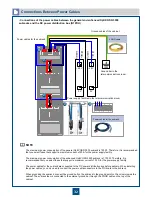
3+0.5 N.M
M6
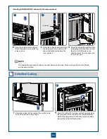
Ground cable
(yellow-green)
Upper cable
tray
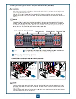
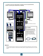
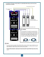
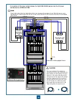
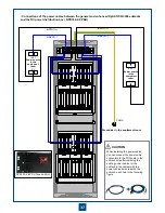
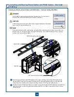
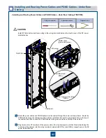
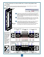
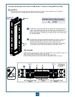
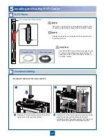
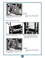
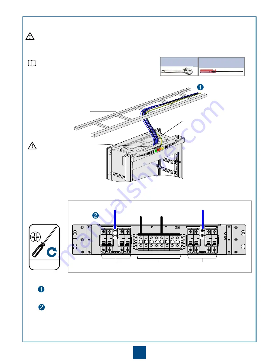
Bind the power cables in a bundle. Route the external power cables and ground cable through the upper cable
tray. Particularly, connect the ground cable to the ground bolt at the top of the cabinet; thread the external
power cables into the cabinet through the cable holes and connect them to the DC input terminals on the DC
PDU at the top of the cabinet.
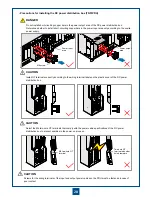
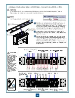
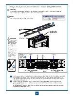
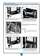
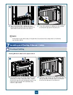
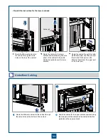
If copper fittings have been installed in the power input areas, put the cord end terminal of each black
power cable (BGND cable) on the RTN(+) input terminal on the PDU with the fluted side facing outward.
Then tighten the screws.
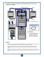
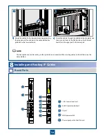
Put the two-hole OT terminal of each blue -48 V power cable on the NEG(-) input terminal on the PDU with
the protruding side facing outward.
M8 screw
PDU with 4-
in-1 short-
circuiting
copper bars
A1-4 (-)
B1-4 (-)
A1
(+)
B1
(+)
•
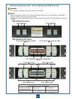
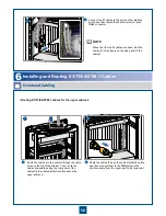
Installing and Routing Power Cables and PGND Cables
– Overhead Cabling (DPD100-2-8 PDU)
Do not install or remove power cables while the equipment is powered on. Ensure that the power is switched
off prior to removing or installing a power cable to avoid bodily injuries.
Install the ground cable prior to the power cables.
NOTE
CAUTION
Phillips screwdriver
Adjustable wrench
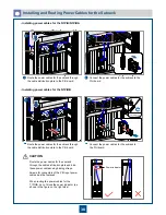
When input terminals
on the PDU do not
need to be connected
with copper fittings,
both the blue -48 V
power cables and
BGND cables must
use cord end
terminals.
When input terminals
on the PDU have
been connected with
copper fittings,
the blue -48 V power
cables must use two-
hole OT terminals
instead of cord end
terminals.
CAUTION
BGND cables (black)
RTN(+)
-48 V power cables (blue)
NEG(-)
-48 V power cables (blue)
NEG(-)

