56
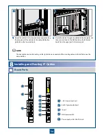
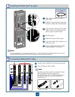
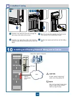
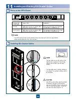
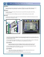
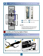
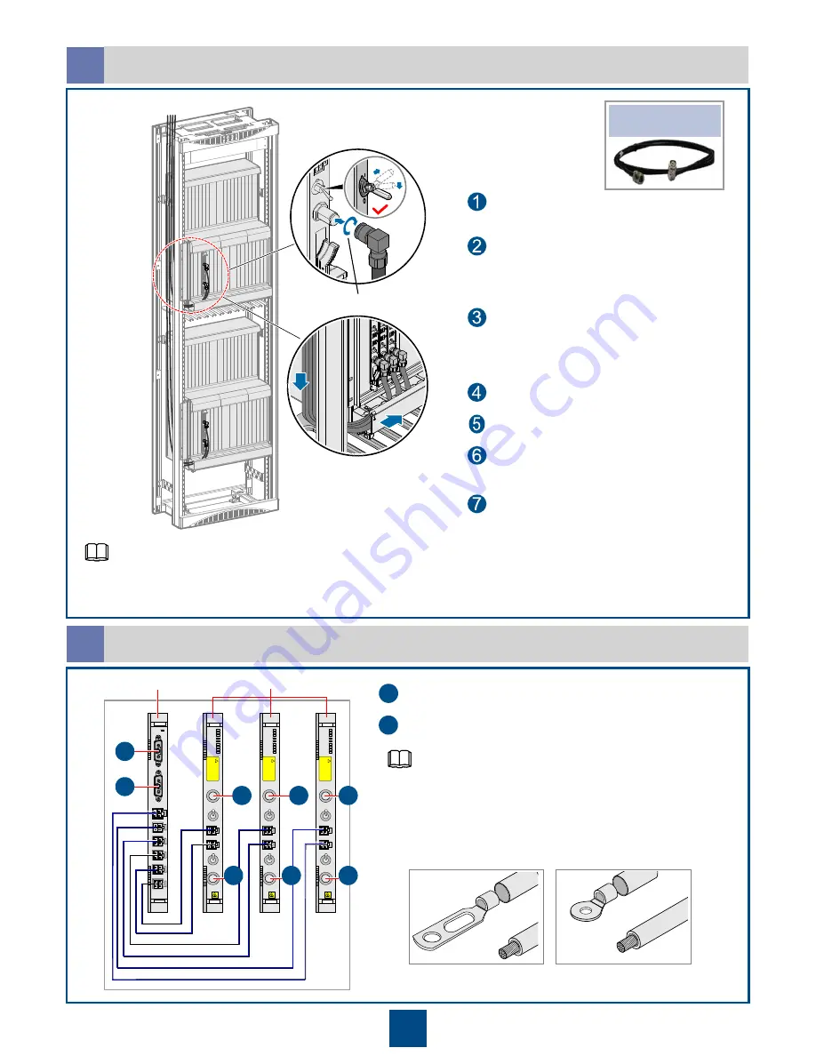
Installing and Routing IF Jumpers
b
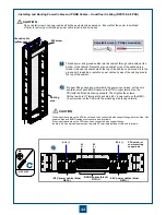
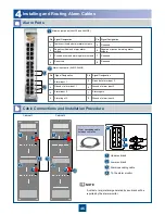
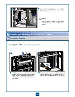
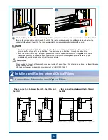
Connect IF power cables to the 20 A power input terminal.
Connect IF jumpers to the IF cables.
2
1
P
O
W
E
R
6
P
O
W
E
R
5
RPWR
RPWR
P
O
W
E
R
2
P
O
W
E
R
1
P
O
W
E
R
3
P
O
W
E
R
4
N
E
G
(-
)
R
T
N
(+
)
N
E
G
(-
)
R
T
N
(+
)
STAT
IFSD1
IFSD
1
IF1
ODU- PWR1
STAT
PROG
SRV
ODU1
LINK2
LINK1
ACT2
ODU2
ACT1
ODU- PWR2
I
IF2
W
A
R
N
IN
G
-4
8
V
O
U
T
P
U
T
T
U
R
N
O
FF
P
O
W
E
R
B
E
F
O
R
E
D
IS
C
O
N
N
E
C
TIN
G
IF
C
A
B
LE
PWR1
PWR2
O
I
O
!
IFSD 1
IFSD
1
IF1
ODU- PWR1
STAT
PROG
SRV
ODU1
LINK2
LINK1
ACT2
ODU2
ACT1
ODU- PWR2
I
IF2
W
A
R
N
IN
G
-4
8
V
O
U
T
P
U
T
T
U
R
N
O
FF
P
O
W
E
R
B
E
F
O
R
E
D
IS
C
O
N
N
E
C
TIN
G
IF
C
A
B
LE
PWR1
PWR2
O
I
O
!
IFSD 1
IFSD
1
IF1
ODU- PWR1
STAT
PROG
SRV
ODU1
LINK2
LINK1
ACT2
ODU2
ACT1
ODU- PWR2
I
IF2
W
A
R
N
IN
G
-4
8
V
O
U
T
P
U
T
T
U
R
N
O
FF
P
O
W
E
R
B
E
F
O
R
E
D
IS
C
O
N
N
E
C
TIN
G
IF
C
A
B
LE
PWR1
PWR2
O
I
O
!
RPWR
FSD1
A
A
B
B
B
B
B
B
1
1
2
2
2
2
2
2
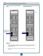
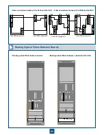
Connections Between IF Cables
c
The preceding steps are only applicable to the RG-8U or ½ -inch IF cables. When the 5D IF cables are used, route
the cables along the cable area on the cabinet side panel to the IF ports on the IF board.
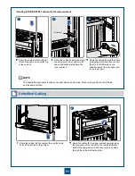
Connect the TNC connector of the IF jumper
to the IF port of the IF interface board and
reserve a proper length of IF jumper.
Bind the IF jumper.
Fasten the connector of the IF jumper.
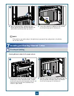
Route the IF jumper through the cable hole
outside the cabinet to the IF interface board.
Attach temporary labels to both ends of
the IF jumper.
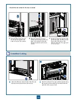
Connect the IF cable to the IF jumper on the
cable tray securely.
Remove the temporary labels and attach
engineering labels to the IF jumper.
IF cable
Moment: 0.8~1.1 N·
M
Assemble a connector on site for one end of the IF power
cable according to the actual condition of the
telecommunications room. For information about how to
assemble the connector, see the "Assembling Cable
Connectors" part.
Two-hole OT terminal
One-hole OT terminal
NOTE
NOTE

