background image

FusionDC1000B Prefabricated Modular Data

Center

Quick Guide (2020, Nigeria,

Platform Capital Refinery DC)

Issue

01

Date

2021-01-05

HUAWEI TECHNOLOGIES CO., LTD.

Содержание FusionDC1000B

Страница 1: ...FusionDC1000B Prefabricated Modular Data Center Quick Guide 2020 Nigeria Platform Capital Refinery DC Issue 01 Date 2021 01 05 HUAWEI TECHNOLOGIES CO LTD ...

Страница 2: ...s document may not be within the purchase scope or the usage scope Unless otherwise specified in the contract all statements information and recommendations in this document are provided AS IS without warranties guarantees or representations of any kind either express or implied The information in this document is subject to change without notice Every effort has been made in the preparation of th...

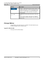
Страница 3: ...neers System engineers Commissioning engineers Data configuration engineers Symbol Conventions The symbols that may be found in this document are defined as follows Symbol Description Indicates a hazard with a high level of risk which if not avoided will result in death or serious injury Indicates a hazard with a medium level of risk which if not avoided could result in death or serious injury Ind...

Страница 4: ... text NOTE is used to address information not related to personal injury equipment damage and environment deterioration Change History Changes between document issues are cumulative The latest document issue contains all updates made in previous issues Issue 01 2021 01 05 This issue is the first official release FusionDC1000B Prefabricated Modular Data Center Quick Guide 2020 Nigeria Platform Capi...

Страница 5: ...e fab Modules 3 3 Installation Drawings 23 4 Removing Transport Protection Materials 24 5 Initial Configuration Parameters 25 A Common Torque Selection Table 26 FusionDC1000B Prefabricated Modular Data Center Quick Guide 2020 Nigeria Platform Capital Refinery DC Contents Issue 01 2021 01 05 Copyright Huawei Technologies Co Ltd iv ...

Страница 6: ...al support Huawei shall not be responsible for any loss caused by unauthorized configuration modification You can modify initial configurations under the guidance of Huawei engineers Huawei assumes no liability for any loss caused by unauthorized changes to the initial configurations Some parameters mentioned in this document should be provided and configured by onsite technical support engineers ...

Страница 7: ... fab module Table 1 1 Reference documentation Item Document Name FusionModul e FusionDC1000B Prefabricated Modular Data Center V100R021C00 Installation Guide FusionDC1000B Prefabricated Modular Data Center V100R021C00 Commissioning Guide FusionDC1000B Prefabricated Modular Data Center V100R021C00 Maintenance Guide UPS UPS5000 E 50 kVA 300 kVA User Manual 50 kVA Power Module Smart cooling product N...

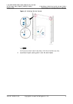
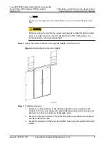
Страница 8: ...accessories Skill requirement common technician Procedure Step 1 Assemble the door frame 1 Open the post covers 2 Secure the door header to the two posts using screws FusionDC1000B Prefabricated Modular Data Center Quick Guide 2020 Nigeria Platform Capital Refinery DC 2 Installing an Aisle Door and an Access Control Device Between Combined Pre fab Modules Issue 01 2021 01 05 Copyright Huawei Techn...

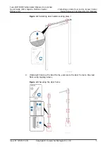
Страница 9: ...ssembly 3 Install door header sealing plate 1 onto the door header FusionDC1000B Prefabricated Modular Data Center Quick Guide 2020 Nigeria Platform Capital Refinery DC 2 Installing an Aisle Door and an Access Control Device Between Combined Pre fab Modules Issue 01 2021 01 05 Copyright Huawei Technologies Co Ltd 4 ...

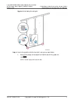
Страница 10: ... steel floor using tapping screws Figure 2 3 Securing the door frame FusionDC1000B Prefabricated Modular Data Center Quick Guide 2020 Nigeria Platform Capital Refinery DC 2 Installing an Aisle Door and an Access Control Device Between Combined Pre fab Modules Issue 01 2021 01 05 Copyright Huawei Technologies Co Ltd 5 ...

Страница 11: ...s 1 Rotate the rubber position in the damper adjust the inner spacing of the damper to 14 mm and reduce the vertical distance between the damper and the door to reduce the vibration of the glass door 2 Secure the damper fastener to the aisle door post using M4x8 cross recessed countersunk head screws 3 Secure the damper and fastener using M4x8 cross recessed countersunk head screws FusionDC1000B P...

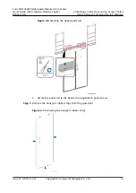
Страница 12: ...ers from both ends of the guide rail NOTE Set the removed plugs and bumpers aside FusionDC1000B Prefabricated Modular Data Center Quick Guide 2020 Nigeria Platform Capital Refinery DC 2 Installing an Aisle Door and an Access Control Device Between Combined Pre fab Modules Issue 01 2021 01 05 Copyright Huawei Technologies Co Ltd 7 ...

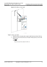
Страница 13: ...rt rubber strips from the glass door Figure 2 7 Removing the transport rubber strips FusionDC1000B Prefabricated Modular Data Center Quick Guide 2020 Nigeria Platform Capital Refinery DC 2 Installing an Aisle Door and an Access Control Device Between Combined Pre fab Modules Issue 01 2021 01 05 Copyright Huawei Technologies Co Ltd 8 ...

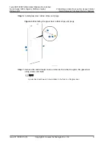
Страница 14: ...ough to the glass door using screws and studs NOTE A protective sheath needs to be installed in the holes on the glass door FusionDC1000B Prefabricated Modular Data Center Quick Guide 2020 Nigeria Platform Capital Refinery DC 2 Installing an Aisle Door and an Access Control Device Between Combined Pre fab Modules Issue 01 2021 01 05 Copyright Huawei Technologies Co Ltd 9 ...

Страница 15: ... secure the card reader bottom plate and remove the bottom plate NOTE Keep the removed screws properly for later use FusionDC1000B Prefabricated Modular Data Center Quick Guide 2020 Nigeria Platform Capital Refinery DC 2 Installing an Aisle Door and an Access Control Device Between Combined Pre fab Modules Issue 01 2021 01 05 Copyright Huawei Technologies Co Ltd 10 ...

Страница 16: ...ove the cable connector route the cable and reinstall the cable connector 5 Secure the card reader to the bottom plate 6 Put the card reader cable in the cable trough and install the cover for the cable trough FusionDC1000B Prefabricated Modular Data Center Quick Guide 2020 Nigeria Platform Capital Refinery DC 2 Installing an Aisle Door and an Access Control Device Between Combined Pre fab Modules...

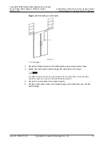
Страница 17: ...h the aisle door panels into the guide rail from both ends FusionDC1000B Prefabricated Modular Data Center Quick Guide 2020 Nigeria Platform Capital Refinery DC 2 Installing an Aisle Door and an Access Control Device Between Combined Pre fab Modules Issue 01 2021 01 05 Copyright Huawei Technologies Co Ltd 12 ...

Страница 18: ...ep 10 Level the aisle door 1 Adjust the height of the fixed arm and verify that the upper surface of the guide rail is flush with the upper surface of the door header FusionDC1000B Prefabricated Modular Data Center Quick Guide 2020 Nigeria Platform Capital Refinery DC 2 Installing an Aisle Door and an Access Control Device Between Combined Pre fab Modules Issue 01 2021 01 05 Copyright Huawei Techn...

Страница 19: ... Step 12 Install the cable chain 1 Install the cable chain fastener onto the glass door NOTE A protective sheath needs to be installed in the holes on the glass door FusionDC1000B Prefabricated Modular Data Center Quick Guide 2020 Nigeria Platform Capital Refinery DC 2 Installing an Aisle Door and an Access Control Device Between Combined Pre fab Modules Issue 01 2021 01 05 Copyright Huawei Techno...

Страница 20: ...n the cable chain fastener FusionDC1000B Prefabricated Modular Data Center Quick Guide 2020 Nigeria Platform Capital Refinery DC 2 Installing an Aisle Door and an Access Control Device Between Combined Pre fab Modules Issue 01 2021 01 05 Copyright Huawei Technologies Co Ltd 15 ...

Страница 21: ...ic lock fasteners 1 and 2 as shown by 2 and 3 in Figure 2 17 3 Connect cables to the magnetic lock by referring to the Connecting Cables chapter FusionDC1000B Prefabricated Modular Data Center Quick Guide 2020 Nigeria Platform Capital Refinery DC 2 Installing an Aisle Door and an Access Control Device Between Combined Pre fab Modules Issue 01 2021 01 05 Copyright Huawei Technologies Co Ltd 16 ...

Страница 22: ...m the button installation position 2 Secure a button to the post using the delivered nut FusionDC1000B Prefabricated Modular Data Center Quick Guide 2020 Nigeria Platform Capital Refinery DC 2 Installing an Aisle Door and an Access Control Device Between Combined Pre fab Modules Issue 01 2021 01 05 Copyright Huawei Technologies Co Ltd 17 ...

Страница 23: ...ll the post covers Figure 2 19 Installing post covers Step 15 Secure door header sealing plates 1 and 2 using bolt assemblies FusionDC1000B Prefabricated Modular Data Center Quick Guide 2020 Nigeria Platform Capital Refinery DC 2 Installing an Aisle Door and an Access Control Device Between Combined Pre fab Modules Issue 01 2021 01 05 Copyright Huawei Technologies Co Ltd 18 ...

Страница 24: ...p of the door header using four M6x16 screws FusionDC1000B Prefabricated Modular Data Center Quick Guide 2020 Nigeria Platform Capital Refinery DC 2 Installing an Aisle Door and an Access Control Device Between Combined Pre fab Modules Issue 01 2021 01 05 Copyright Huawei Technologies Co Ltd 19 ...

Страница 25: ... installation position and secure it on the inner side FusionDC1000B Prefabricated Modular Data Center Quick Guide 2020 Nigeria Platform Capital Refinery DC 2 Installing an Aisle Door and an Access Control Device Between Combined Pre fab Modules Issue 01 2021 01 05 Copyright Huawei Technologies Co Ltd 20 ...

Страница 26: ... device based on the installation diagram for the corresponding solution FusionDC1000B Prefabricated Modular Data Center Quick Guide 2020 Nigeria Platform Capital Refinery DC 2 Installing an Aisle Door and an Access Control Device Between Combined Pre fab Modules Issue 01 2021 01 05 Copyright Huawei Technologies Co Ltd 21 ...

Страница 27: ...ock 4 Emergency button 5 Card reader 6 Exit button End FusionDC1000B Prefabricated Modular Data Center Quick Guide 2020 Nigeria Platform Capital Refinery DC 2 Installing an Aisle Door and an Access Control Device Between Combined Pre fab Modules Issue 01 2021 01 05 Copyright Huawei Technologies Co Ltd 22 ...

Страница 28: ...stallation Drawings FusionDC1000B Prefabricated Modular Data Center Quick Guide 2020 Nigeria Platform Capital Refinery DC 3 Installation Drawings Issue 01 2021 01 05 Copyright Huawei Technologies Co Ltd 23 ...

Страница 29: ...ith the Previous Pre fab Module Installing Supportive Columns Hoisting and Securing Pre fab Modules Mounting Base Solution Removing Supportive Columns Securing Pre fab Modules Securing Pre fab Modules NO S005 Pre fab Module Securing Position Diagram Obtaining the Emergent Backup Obtaining the Emergent Backup Key N A Disabling the Door Closer Disabling the Door Closer N A Installing External Sealin...

Страница 30: ...tion Diagram Prepared Onsite Installing Water Refill Pipes Installing Drainpipes Installing an Electrical Actuator Installing Batteries for the ASD Power Box Installing Batteries for the Extinguishant Control Panel Installing Aisle Doors Between Combined Pre fab Modules Installing Aisle Doors for a Single Module Installing Internal Cable Trays Between Combined Pre fab Modules NO S020 Position Diag...

Страница 31: ...ring Diagram Connecting Monitoring Cables NO M006 Monitoring System Onsite Wiring Diagram Connecting MDB GIU Cables Connecting MDB GIU Cables NO P010 MDB GIU Wiring Diagram Connecting rPDU Cables Connecting rPDU Cables NO P011 rPDU Wiring Diagram Connecting Cables Between Functional Zones Connecting the Power Cable to the Maintenance Socket NO P012 Socket Wiring Diagram Connecting Cables to Lighti...

Страница 32: ...allation Diagram Removing Transport Protection Materials on Top of Aisles Removing Transport Protection Materials on Top of Aisles NO F001 Fire Extinguishing Device Layout Diagram see the initial configuration Removing Air Conditioner Compressor Fasteners Removing Air Conditioner Compressor Fasteners Removing the Pump Float Baffle Plate 35 kW Removing the Pump Float Baffle Plate Resetting the Door...

Страница 33: ...nly four mounting holes are required The external four holes are preferred If the external holes are conflict with the concrete podium or ground reinforcement use the internal holes 2 Dual capacity bases are installed in the middle and single capacity bases are installed on the upper and lower sides Ensure that the direction of the bases is consistent with that in the drawing 3 Single capacity and...

Страница 34: ... and then remove the remaining EPS panels in sequence according to the removal direction shown in the figure 3 Remove the remaining edge wraps marked 6 in the figure of the transport side wall and then remove the remaining beams and columns marked 7 in the figure of the transport side wall 2 Front distance block Enlarged at 10 1 1 Side combination distance block Enlarged at 10 1 1 Combination dist...

Страница 35: ... connecting and securing the modules install external sealing materials by referring to NO S006 External Sealing Material Layout Diagram NO S005 Pre fab Module Securing Position Diagram GB9074_17 88_M10X40 12 Connecting plate DKBA61586366 ASM 4 M10X40 bolt No Drawing No Item Qty Remarks 1 2 A2 A1 Top connecting plat Enlarged at 10 1 M10X40 ...

Страница 36: ... install internal bottom sealing kits for combined modules by referring to NO S007Pre fab Module Internal Combining Material Installation Position Diagram 1 Install rubber strip Apply sealant Attach roll Install cover t 2mm DKBA82990596 ASM 6 End clamping plate DKBA82990592 ASM 6 Top clamping plate No Drawing No Item Qty Remarks 1 2 GB9074_4 88_M4X12_S 8 Stainless steel screw 3 4 DKBA04853056_2000...

Страница 37: ...secure the component to the profile surface using tapping screws GB15856_1 2002_ST4_8X25 5 Install the top sealing kits inside combined modules by referring to NO S007 Pre fab Module Internal Combining Material Installation Position Diagram 2 Bottom internal sealing A 3 Armaflex thermal insulation pipe 2 Bottom thermal insulation foam 1 Pre installed 4 Bottom cover leg 6 Bottom cover 1 ESD veneer ...

Страница 38: ...agram Install Armaflex thermal insulation pipe Install end wall rock wool Install partition wall rock wool A End internal sealing A enlarged view 3 Rock wool 1 1 Armaflex thermal insulation pipe 2 Edge wrap Edge wrap B B enlarged view Rock wool 1 End thermal insulation foam Armaflex thermal insulation pipe Edge wrap 6 Internal corner No Drawing No Item Qty Remarks 1 2 3 4 5 6 7 8 DKBA80998528 ASM ...

Страница 39: ...agram Install Armaflex thermal insulation pipe Install end wall rock wool Install partition wall rock wool A End internal sealing A enlarged view 3 Rock wool 1 1 Armaflex thermal insulation pipe 2 Edge wrap Edge wrap B B enlarged view Rock wool 1 End thermal insulation foam Armaflex thermal insulation pipe Edge wrap 6 Internal corner No Drawing No Item Qty Remarks 1 2 3 4 5 6 7 8 DKBA80998528 ASM ...

Страница 40: ... point to connect to the ground grid based on the actual position It is recommended that the ground point at the bottom of the module be used Before grounding remove the foil Tthe grounding bolt is an M12x30 stainless steel hexagon head bolt and needs to be tightned to a torque of 470 toque Pre fab module ground point A A1 A2 B Bolt assembly M12X30 GB9074_17 88_M12X30_S 8 No Drawing No Item Qty Re...

Страница 41: ...ls using M16 bolts delivered with the eaves 2 Install the snow and rain cover on the mounting plate above the fireproof door and then secure the cover on the mounting plate A direction A 25 26 27 28 29 30 31 32 33 34 25 26 27 28 29 30 31 32 33 34 25 26 27 28 29 30 31 32 33 34 25 26 27 28 29 30 31 32 33 34 No Drawing No Item Qty Remarks ...

Страница 42: ...GB9074_17 88_M10X30_S 2 Install the outdoor unit on the top of the pre fab module and secure it using stainless steel GB9074_17 88_M10X30_S screws 3 Install the outdoor unit at the position shown in the figure and secure it using stainless steel GB9074_17 88_M10X30_S screws 4 Install outdoor pipes Bind copper pipes at the pre fab module outlet along the cable binding plate on the rear wall of the ...

Страница 43: ...GB9074_17 88_M10X30_S 2 Install the outdoor unit on the top of the pre fab module and secure it using stainless steel GB9074_17 88_M10X30_S screws 3 Install the outdoor unit at the position shown in the figure and secure it using stainless steel GB9074_17 88_M10X30_S screws 4 Install outdoor pipes Bind copper pipes at the pre fab module outlet along the cable binding plate on the rear wall of the ...

Страница 44: ...ross beam 5 6 DKBA80690726 ASM 8 Air conditioner fastener 7 Reinforcing rib 2 DKBA80716390 ASM 2 55D air conditioner support 3 DKBA61547516 ASM 2 13kw air conditioer side beam 2 8 9 DKBA83116352 ASM 7 13kw air conditioer side beam 1 DKBA83116353 ASM 2 13kw air conditioer cross beam 10 11 DKBA61613967 ASM 2 DKBA81073313 ASM 8 13KW air conditioner support 12 13 DKBA81073313 ASM 8 13KW air conditione...

Страница 45: ......

Страница 46: ......

Страница 47: ...d refrigerant pipe Gas refrigerant pipe C direction B direction A direction Liquid refrigerant pipe Outdoor unit signal cable Outdoor unit power cable Gas refrigerant pipe Liquid refrigerant pipe Gas refrigerant pipe Liquid refrigerant pipe Gas refrigerant pipe Liquid refrigerant pipe Gas refrigerant pipe Liquid refrigerant pipe Gas refrigerant pipe Liquid refrigerant pipe Outdoor unit signal cabl...

Страница 48: ... Extinguishant Control Panel DH 1 Horn Strobe DH 2 Abort Switch DH 1 Fire Alarm Bell DH 1 Electrical Actuator DH 1 Warning Signs DH 1 Emergency Lighting DH 3 Pneumatic Switch DH 1 B Emergency Lighting D P Horn Strobe DH 1 Emergency Lighting Emergency Lighting DH 2 Emergency Lighting Connecting Cables to the Fire Control Panel Batteries Onsite 1 2 3 No Name Quantity 1 12V 7 2Ah ASD Batteries 6pcs 2...

Страница 49: ...h accessories 1 NO S019 Combined Module Aisle Door Installation Position Diagram 25 26 27 28 29 30 31 32 33 34 25 26 27 28 29 30 31 32 33 34 25 26 27 28 29 30 31 32 33 34 25 26 27 28 29 30 31 32 33 34 DKBA61777720 ASM ...

Страница 50: ...awing No Item Qty Remarks 1 2 DKBA61595926 ASM 1 Optical fiber cable trough DKBA83117985 ASM 1 Front aluminum profile cable tray 3 4 With connector With connector With connector With connector 34 33 32 31 30 29 28 27 26 25 34 33 32 31 30 29 28 27 26 25 34 33 32 31 30 29 28 27 26 25 34 33 32 31 30 29 28 27 26 25 3 Optical fiber cable trough 2 Mesh cable tray 4 Front aluminum profile cable tray 1 3 ...

Страница 51: ......

Страница 52: ......

Страница 53: ......

Страница 54: ......

Страница 55: ......

Страница 56: ......

Страница 57: ...am A1 Module DKBA04853262_E 1 Connecting plate 28 Note 1 Install the upper corner fittings of the suspenders in the following sequence 1 Install the lower layer straight section corner fittings of the suspenders as shown in the figure 2 Install the upper layer straight section corner fittings of the suspendiers as shown in the figure GB9074_13 88_M6X16 ...

Страница 58: ...am A2 Module DKBA04853262_E 1 Connecting plate 28 Note 1 Install the upper corner fittings of the suspenders in the following sequence 1 Install the lower layer straight section corner fittings of the suspenders as shown in the figure 2 Install the upper layer straight section corner fittings of the suspendiers as shown in the figure GB9074_13 88_M6X16 ...

Страница 59: ......

Страница 60: ......

Страница 61: ......

Страница 62: ...on is connected to the access control actuator using a network cable 4 Crimp RJ45 connectors at both ends of the network cable using the T568B connection method Connect the network port connector to the door button 5 Connect the card reader to the access actuator using a network cable 6 Crimp RJ45 connectors at both ends of the network cable using the T568B connection method 1 2 3 4 RED male femal...

Страница 63: ...ller Panel 24 24 23 1U Filler Panel 23 23 22 1U Filler Panel 22 22 21 1U Filler Panel 21 21 20 1U Filler Panel 20 20 19 1U Filler Panel 19 19 18 1U Filler Panel 18 18 17 1U Filler Panel 17 17 16 1U Filler Panel 16 16 15 1U Filler Panel 15 Cable Manager 15 14 1U Filler Panel 14 14 13 1U Filler Panel 13 13 12 1U Filler Panel 12 12 11 1U Filler Panel 11 11 10 1U Filler Panel 10 10 9 1U Filler Panel 9...

Страница 64: ...l 22 22 21 1U Filler Panel 21 21 20 1U Filler Panel 20 20 19 1U Filler Panel 19 19 18 1U Filler Panel 18 18 17 1U Filler Panel 17 17 16 1U Filler Panel 16 16 15 1U Filler Panel 15 Cable Manager 15 14 1U Filler Panel 14 14 13 1U Filler Panel 13 13 12 1U Filler Panel 12 12 11 1U Filler Panel 11 11 10 1U Filler Panel 10 10 9 1U Filler Panel 9 9 L Type Guide Rail 8 1U Filler Panel 8 8 L Type Guide Rai...

Страница 65: ... Type Guide Rail 3 UIM20A PR A1 3 3 2 Cable Tray 2 RPDU 2 1 UIM20A PR A2 1 RPDU 1 Rack front Rack back 6 Collector_ECC800 PR B1 6 6 L Type Guide Rail 5 Cable Tray 5 5 4 UIM20A PR B1 4 4 3 Cable Tray 3 3 2 UIM20A PR B2 2 RPDU 2 1 Cable Tray 1 RPDU 1 Guide Rail config Guide Rail config Power Room A Power Room B ...

Страница 66: ...tor DH 3 A102 1 PCS 3 A101 A102 25033402 Electronic Electric Cable 300V UL3385 16AWG Tin Plating Black LSZH UL 1 PCS No Module Input device Module Output device Code No Description QTY Unit Input Output 4 A101 A102 25033402 005 Electronic Electric Cable 300V UL3385 16AWG Tin Plating Red LSZH UL 1 PCS Smoke Detector DH 5 Heat Detector DH 5 Smoke Detector DH 3 Heat Detector DH 3 Smoke Detector DH 5 ...

Страница 67: ...5050057 Twisted Pair Cable 100ohm Category 5e FTP 0 52mm 24AWG 8Cores 4Pairs PANTONE 430U Use with Plug 14080097 1 PCS Install VCN onsite 2 A101 GIU DH A2 A102 GIU DH B1 25050057 Twisted Pair Cable 100ohm Category 5e FTP 0 52mm 24AWG 8Cores 4Pairs PANTONE 430U Use with Plug 14080097 1 PCS 3 A101 A102 25033402 Electronic Electric Cable 300V UL3385 16AWG Tin Plating Black LSZH UL 1 PCS 5 A102 A101 2...

Страница 68: ......

Страница 69: ......

Страница 70: ......

Страница 71: ......

Страница 72: ......

Страница 73: ......

Страница 74: ...ire retardant bags 1 1 1 E E E E sectional view Fire retardant bag installation Brush NO S022 Fire Retardant Bag Installation Position Diagram 25 26 27 28 29 30 31 32 33 34 25 26 27 28 29 30 31 32 33 34 25 26 27 28 29 30 31 32 33 34 25 26 27 28 29 30 31 32 33 34 1 ...

Страница 75: ...he second adjacent blind plate on the ceiling keel from the other side by following the same method and requirements and install the corresponding blind plate clamping corner 1 Install the remaining two rows of blind plates in the same way 1 2 4 Blind plate 3 4 Blind plate 3 6 Blind plate clamping corner 1 Step 3 installation diagram Step 4 installation diagram Blind plate 3 installation diagram I...

Страница 76: ...tor PR B1 Smoke Detector PR B1 Exit DH 1 EXIT Heat Detector DH 1 Smoke Detector DH 1 Heat Detector DH 2 Smoke Detector DH 2 Heat Detector DH 3 Smoke Detector DH 3 Heat Detector DH 4 Smoke Detector DH 4 Heat Detector DH 5 Smoke Detector DH 5 Heat Detector DH 6 Smoke Detector DH 6 NO F001 Fire Extinguishing Device Layout Diagram CE ...

Страница 77: ......

Страница 78: ...uring tape 5 Smoke detector Securing tape and red cover 6 Heat detector Securing tape and red cover 7 Fire alarm horn strobe Securing tape 8 Fire alarm bell Securing tape 9 Emergency light Securing tape 10 T H sensor Securing tape 11 Camera Securing tape 12 Emergency door release button Plastic cover FusionDC1000B Prefabricated Modular Data Center Quick Guide 2020 Nigeria Platform Capital Refinery...

Страница 79: ...guration Parameters FusionDC1000B Prefabricated Modular Data Center Quick Guide 2020 Nigeria Platform Capital Refinery DC 5 Initial Configuration Parameters Issue 01 2021 01 05 Copyright Huawei Technologies Co Ltd 25 ...

Страница 80: ... Structura l Connecti on Commo n Steel Connecto r Electrical Connection OT DT Terminal Cord End Terminal Block Positive Negative Battery Wiring Terminal M3 Cross recessed small pan head screw assembly Electric screwdriv er 6 6 M4 Cross recessed counters unk head screw cross recessed pan head screw assembly Electric screwdriv er 12 12 14 FusionDC1000B Prefabricated Modular Data Center Quick Guide 2...

Страница 81: ...r 13 kW Air Cooled Smart Cooling Product Initial Temperature and Humidity Configuration Parameters for 13 kW Air Cooled Smart Cooling Product NO M001 Monitoring Device Layout Diagram NO M002 Monitoring System Network Diagram Table 3 Initial Configuration Parameters for the Management System NO F001 Fire Extinguishing Device Layout Diagram CE NO F002 Fire Extinguishing System Conceptual Diagram CE ...

Страница 82: ......

Страница 83: ......

Страница 84: ...volved adjust the voltage and frequency settings based on the local voltage system and check whether the voltage thresholds and frequency hysteresis meet setting requirements before first operation Device Name Project Configuration 8D ATS Involved Not involved Involved Not involved UPS5000 E MCCB SmartLi Involved Not involved Involved Not involved Note The following device parameters are not all p...

Страница 85: ...In Use Generator In Use Line priority Line 1 Switch I Line 1 Switch I Line 2 Switch II No Line Priority Line 1 Switch Volt Threshold Min LN1 20 30 to 5 10 Volt Threshold Min LN2 20 30 to 5 10 Volt Threshold Max LN1 20 5 to 30 10 Volt Threshold Max LN2 20 5 to 30 10 Volt Hysteresis Min LN1 8 29 to 4 step 1 8 Volt Hysteresis Min LN2 8 29 to 4 step 1 8 Volt Hysteresis Max LN1 8 4 to 29 step 1 8 Volt ...

Страница 86: ...N2 3 0 0 8 to 9 8 3 0 Switching 0s 0 60s 0s Dead Band I to II 0s 0 60s 5s Back Switching 0s 0s 1s 59s 1 min 2 min 90 min 0s Dead Band II to I 0s 0 60s 5s Delay on Transfer 0s 0s 1s 59s 1 min 2 min 10 min 30s Generator Stop 5s 0s 1s 59s 1 min 2 min 30 min 10s Chinese English French Italian Spanish Finnish German Russian and Chinese English Frequency Hysteresis Delay Times Device Configuration Langu...

Страница 87: ... Start address 112 Default value Quantity 0 0 12 Default value SSID UPS_WIFI Last six characters of the MAC address Default value Password Changeme Default value Enable Enable Disable Default value 80 Default value Single Single Parallel Single 2 0 0 19 0 Normal mode Normal mode ECO mode Self load mode Converter mode Normal mode 5 5 6 7 8 9 10 5 Non BSC BSC mode Non BSC Non BSC ECO voltage range B...

Страница 88: ...en the voltage level is 380 V 400 V and 415 V respectively 380V 209 0 231 0 400V 218 5 241 5 415V 228 0 252 0 240 50 Hz 50 Hz 60 Hz 50 Hz 0 6 Hz s 0 1Hz s 2 0Hz s 0 6 Hz s Enable Enable Disable Enable 10 1 1440 10 Enable Enable Disable Enable Disable Enable Disable Disable EOD restart delay Output freq track rate Hz s Zero display with no load output EOD restart Calib output current if no load Out...

Страница 89: ...etting Default value Disable Enable Disable Default value Disable Enable Disable Default value English 12 languages including English Chinese Italian and so on English 000001 Default value Enable Enable Disable Enable Cell charge voltage V cell password complexity check Batter breaker iBOX setting Installation time Battery type Bypass frequency range Hz User Settings Language Password Dry Contact ...

Страница 90: ...attery temp abnormal Battery undervolt Set as required DO_1 action Closed Closed Open Default value DO_2 None None Critical alarm Minor alarm Fire extinguisher started Battery temp abnormal Battery undervolt Set as required DO_2 action Closed Closed Open Default value Battery EPO Disable Enable Disable Default value Copper bar overtemp Enable Enable Disable Default value Fire cylinder pressure abn...

Страница 91: ...m a MAX MAX MED MIN MIN MCCB Current Parameter Settings Category Parameter Component MDB A 2QF3 MDB A 2QF4 MDB B 2QF3 MDB B 2QF4 GIU DH A1 QF GIU DH A2 QF GIU DH B1 QF GIU DH B2 QF Pyromagnetic MCCB current setting Pyromagnetic MCCB current setting ...

Страница 92: ......

Страница 93: ......

Страница 94: ......

Страница 95: ... CRAH DH B2 1 2 YES Enable CAN network 2 2 Enable 7day s 0 NO Anti competitive running Enable Room Air conditioner Teamwork function Air conditioner address Enable Teamwork resistor Number of smart cooling products in this group Number of running smart cooling products in this group Rotation function Rotation Type Rotation period Rotation time High Temp Start All Temp for HT Start All Low Temp Sta...

Страница 96: ... Parameters for 55 kW Air Cooled Smart Cooling Product Temperature and humidity control type Initial Temperature and Humidity Configuration Parameters for 13 kW Air Cooled Smart Cooling Product Air Conditioner CRAH PR A1 Average vaue 23 40 10 Control point temperature setpoint Humidity deadband Administrator can change it in advanced settings 10 Supply air Supply air PR PR CRAH PR B2 40 DH DH CRAH...

Страница 97: ...0 CH Kind of action Cooling cL Heating Ht cL cL Ht Ht id Interval between defrost cycles 6 0 99 hours 0 Md Maximum length for defrost 30 0 99 min 0 dF Display during defrost rt Actual storage temperature it Store temperature before frost start St Set Point dF dF thawing character it rt it St dF it Adjusting Parameters Defrost Parameters Initial Configuration Parameters for Ventilation Window Elect...

Страница 98: ...Window CB DH 1 Window CB PR B1 ECC NO M001 Monitoring Device Layout Diagram ...

Страница 99: ...r_ECC800 PR A1 TH PR B1 MDB B_SPD2 UIM20A PR A1 UIM20A PR A2 Reserved Reserved Reserved Reserved Reserved Reserved Reserved Reserved Reserved Collector_ECC800 PR B1 UIM20A PR B1 UIM20A PR B2 Reserved Reserved Reserved FIRE RELAY LOCAL FIRE FAULT RELAY Extinguishant Control Panel CE Extinguishant Control Panel CE FIRE RELAY LOCAL FIRE FAULT RELAY Extinguishant Control Panel CE Extinguishant Control...

Страница 100: ...rt 2 Initial IP 192 168 0 120 Initial password HuaWei123 LAN Switch DH 1 FE 02353BNP IP Camera DH 2 C3220 10 IU 192 168 9 16 User name admin Initial password Huawei123 LAN LAN Switch PR A1 Port 4 Initial IP 192 168 0 120 Initial password HuaWei123 LAN Switch DH 1 FE 02353BNP IP Camera DH 3 C3220 10 IU 192 168 9 17 User name admin Initial password Huawei123 LAN LAN Switch DH 1 Port 4 Initial IP 192...

Страница 101: ...artLi 512V 80AH F 01 192 168 9 25 User name admin Initial password Changeme User name admin Initial password 000001 FE LAN Switch DH 1 Port 11 LAN Switch PR A1 FE 02312TDM IT UPS BAT A SmartLi 512V 80AH F 01 192 168 9 26 User name admin Initial password Changeme User name admin Initial password 000001 FE LAN Switch PR A1 Port 5 LAN Switch PR A1 FE 02312TDM IT UPS BAT B SmartLi 512V 80AH F 01 192 1...

Страница 102: ...itial IP192 168 248 10 Collector_ECC8 00 DH 1 FE 02312RHH 001 GIU DH B2 NMW 0250A4 GIU M02 FE Collector_ECC8 00 DH 1 LAN1 Collector_ECC8 00 DH 1 FE 02312RHL PDU DH B2 1 NMW 125A4 6 0 M02 FE_2 GIU DH B2 FE_1 Collector_ECC8 00 DH 1 FE 02312RHL PDU DH B2 2 NMW 125A4 6 0 M02 FE_2 PDU DH B2 1 FE_1 Collector_ECC8 00 DH 1 FE 02312RHL PDU DH B2 3 NMW 125A4 6 0 M02 FE_2 PDU DH B2 2 FE_1 Collector_ECC8 00 D...

Страница 103: ...DH 1 RS485 52274559 CRAH DH A1 NetCol8000 A055D4WD4 1 User Name admin password 000001 COM FE UIM20A DH 1 COM1 Collector_ECC8 00 DH 1 RS485 52274559 CRAH DH A2 NetCol8000 A055D4WD4 1 User Name admin password 000001 COM FE UIM20A DH 1 COM2 Collector_ECC8 00 DH 1 RS485 52274559 CRAH DH B1 NetCol8000 A055D4WD4 1 User Name admin password 000001 COM FE UIM20A DH 2 COM1 Collector_ECC8 00 DH 1 RS485 52274...

Страница 104: ...m severity critical RJ45 Collector_ECC8 00 DH 1 COM2 Collector_ECC8 00 PR A1 RS485 33010346 TH PR A1 LH WS46 HW 1 Temperature 10C 30C Humidity 20 RH 80 RH Alarm severity critical RJ45 UIM20A PR A2 COM1 Collector_ECC8 00 PR B1 RS485 33010346 TH PR B1 LH WS46 HW 1 Temperature 10C 30C Humidity 20 RH 80 RH Alarm severity critical RJ45 UIM20A PR B2 COM1 Collector_ECC8 00 DH 1 RS485 CRAC PDB DH A_METER ...

Страница 105: ...3 LOCAL FIRE Normal open Alarm closed Crimping terminal Collector_ECC8 00 PR A1 AIDI_2 Collector_ECC8 00 PR A1 dry contact 52250103 FIRE RELAY Normal open Alarm closed Crimping terminal Collector_ECC8 00 PR A1 AIDI_3 Collector_ECC8 00 PR B1 dry contact 52250103 FAULT RELAY Normal open Alarm closed Crimping terminal Collector_ECC8 00 PR B1 AIDI_1 Collector_ECC8 00 PR B1 dry contact 52250103 LOCAL F...

Страница 106: ...mal closed Alarm open RJ45 UIM20A PR A2 AI DI_3 Collector_ECC8 00 PR B1 dry contact 33010347 Leakage Sensor PR B1 Normal closed Alarm open RJ45 UIM20A PR B2 AI DI_3 Collector_ECC8 00 1 dry contact CRAC PDB DH A_SPD Normal closed Alarm open Crimping terminal UIM20A DH 1 AI DI_5 Collector_ECC8 00 1 dry contact CRAC PDB DH B_SPD Normal closed Alarm open Crimping terminal UIM20A DH 2 AI DI_5 Collector...

Страница 107: ...tor_ECC8 00 PR B1 dry contact MDB B_SPD1 Normal closed Alarm open Crimping terminal UIM20A PR B1 AI DI_5 Collector_ECC8 00 PR B1 dry contact MDB B_SPD2 Normal closed Alarm open Crimping terminal UIM20A PR B1 AI DI_6 Collector_ECC8 00 PR B1 dry contact CRAC PDB PR B_SPD Normal closed Alarm open Crimping terminal UIM20A PR B1 AI DI_7 Collector_ECC8 00 PR B1 dry contact Lighting PDB PR B_SPD Normal c...

Страница 108: ...Energy efficiency management Mobile app O M Whether the optional functions of the NetEco software are configured Function After a camera is commissioned label the camera with its name and IP address Number of hard disks extra configured for the VCN520 1 ...

Страница 109: ...tor PR B1 Smoke Detector PR B1 Exit DH 1 EXIT Heat Detector DH 1 Smoke Detector DH 1 Heat Detector DH 2 Smoke Detector DH 2 Heat Detector DH 3 Smoke Detector DH 3 Heat Detector DH 4 Smoke Detector DH 4 Heat Detector DH 5 Smoke Detector DH 5 Heat Detector DH 6 Smoke Detector DH 6 NO F001 Fire Extinguishing Device Layout Diagram CE ...

Страница 110: ...NO F002 Fire Extinguishing System Conceptual Diagram CE ...

Страница 111: ...NO F002 Fire Extinguishing System Conceptual Diagram CE ...

Страница 112: ...NO F002 Fire Extinguishing System Conceptual Diagram CE ...

Страница 113: ...NO F002 Fire Extinguishing System Conceptual Diagram CE ...

Страница 114: ...NO F002 Fire Extinguishing System Conceptual Diagram CE ...

Страница 115: ...NO F002 Fire Extinguishing System Conceptual Diagram CE ...

Страница 116: ...NO F002 Fire Extinguishing System Conceptual Diagram CE ...

Страница 117: ...NO F002 Fire Extinguishing System Conceptual Diagram CE ...

Страница 118: ...NO F002 Fire Extinguishing System Conceptual Diagram CE ...

Страница 119: ......

Страница 120: ...Window CB DH 1 Window CB PR B1 EXIT Exit DH 3 NO F003 Emergency Exit Diagram ...


Страница 121: ... 30 50 30 50 M8 Cross recessed hexagon head screw assembly Torque wrench 200 130 Cross recessed counters unk head screw Pneumati c screwdriv er 80 M10 Hexagon head screw assembly Torque wrench 400 270 M12 Hexagon head screw assembly Torque wrench 600 470 M16 Common bolt Torque wrench 1600 1200 FusionDC1000B Prefabricated Modular Data Center Quick Guide 2020 Nigeria Platform Capital Refinery DC A C...

Страница 122: ...elf drilling tapping screw Pneumati c screwdriv er 50 for checking not for tightenin g G1 2 1 2 pipe connecto r Torque wrench 350 G3 4 3 4 pipe connecto r Torque wrench 600 G1 1 pipe connecto r Torque wrench 600 FusionDC1000B Prefabricated Modular Data Center Quick Guide 2020 Nigeria Platform Capital Refinery DC A Common Torque Selection Table Issue 01 2021 01 05 Copyright Huawei Technologies Co L...

Отзывы: