66
7 Installing the Electronic Door Lock System
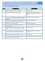
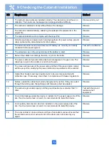
7.6 Post-Installation Check
No.
To Verify That…
Check Method
1
Boards support easy removal and reinstallation.
Check by trial use.
2
The exterior of the CCU has no paint peeling.
Check the exterior of the CCU. If any paint
peeling is found, repaint the CCU to avoid
rusting.
3
The CCU is securely installed in the cabinet and meets the
anti-quake requirements specified in engineering design
documents.
Check whether the bolts are tightened.
4
The CCU is installed in the right of the cabinet, which meets
the requirement specified in engineering documents.
Check the installation position.
5
The ELU port is connected correctly.
Check the port connection.
6
The door locks are correctly installed, and cables are
correctly connected.
Check the door locks and their connections.
7
Monitoring cables and AC power cables are not bundled
together, and the cables are neatly and securely routed.
Check cable routing.
8
All power cables must use jointless copper cores and
correctly connected according to operation standards.
Check all power cables and power cable
connections.
9
All cables are intact without joints between two ends.
Check all cables.
10
The cabinet interior is clean without foreign materials, and
the air intake/exhaust vent is not blocked.
Check the interior of the cabinet and air vents.
Содержание F01T500
Страница 1: ...HUAWEI TECHNOLOGIES CO LTD F01T500 Quick Installation Guide Issue 07 Date 2017 05 03 ...
Страница 19: ...With battery cabinet 4 Installing the Cabinet on a Concrete Pedestal 14 ...
Страница 23: ...18 Unit mm 4 Installing the Cabinet on a Concrete Pedestal ...
Страница 25: ...20 4 Installing the Cabinet on a Concrete Pedestal ...
Страница 27: ...22 4 Installing the Cabinet on a Concrete Pedestal ...
Страница 36: ...31 Install the power meter box Seal the power meter box Fence the cabient after it is installed ...
Страница 38: ...33 With power meter box ...
Страница 40: ...35 With power meter box AC power cables AC power cables ...
Страница 44: ...39 6 Routing Cables 6 3 Diagram of Cable Connections Between the RPS and MDF RPS Power Supply ...
Страница 49: ...44 6 Routing Cables 6 7 Diagram of Cable Connections Between the RPS and MDF AC RPR Power Supply ...
Страница 51: ...46 Route the input Cables of the AC RPR power supply 6 Routing Cables ...
Страница 83: ...14 FAQs for Installation 78 ...
Страница 84: ...15 FAQs for Installation 79 ...

