21
a fully manual adjustable double pulse. These options
are available regardless of the material (mild steel,
stainless steel, silicon bronze, or aluminum) and wire
diameter. These pulse features work regardless of which
MIG gun you use; air-cooled, water-cooled, spool gun,
or push-pull gun all work equally well with these pulse
features.
Fig. 23
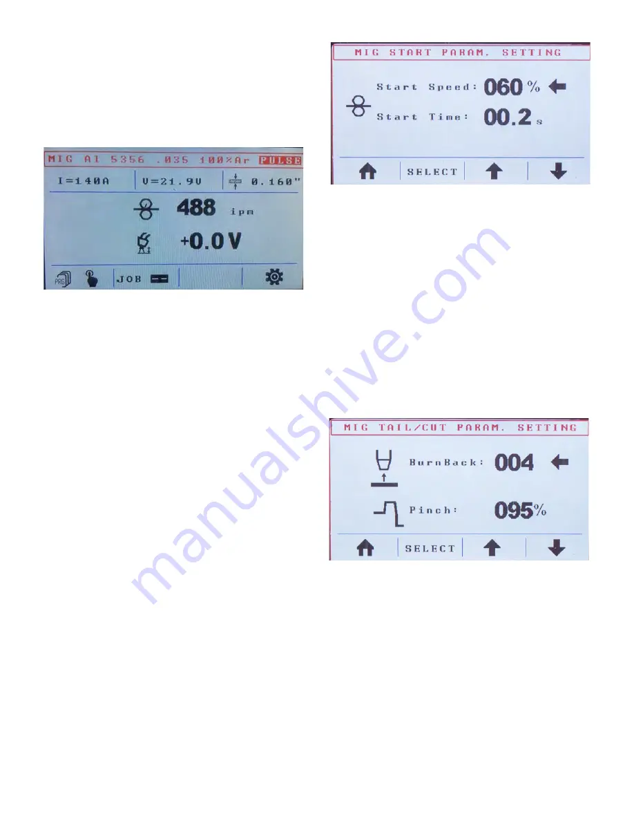
Once you select a program, the program list disappears,
and the program is displayed (
Fig. 23
). The top line in
the display shows the name of the program, the wire
diameter, and the required gas/gas mixture. It also
indicates if it is a synergic or a pulse program. The line
below displays, starting from the left, the approximate
amperage (calculated based on the material, wire speed,
wire diameter, and other variables), arc voltage, and
material thickness. By turning left encoder
F
(
Fig. 4
),
you can adjust the material thickness; adjusting the
material thickness also adjusts, automatically, the wire
speed and the voltage.
In the center of the LCD, the wire speed is displayed in
IPM. Below that, the voltage deviation of the synergic
curve is displayed. This value is supposed to read 0.0 V
at most times, for most welding operations. You can
adjust this value by turning right encoder
G
(
Fig. 4
). If
an adjustment is made, the absolute arc voltage changes,
and the color in the display changes from black to red. A
deviation of the synergic arc does two things: it changes
the arc length and it makes the weld hotter or colder.
However, on a synergic machine, the main heat
adjustment is made with left encoder
F
(
Fig. 4
) by
setting the material thickness. The voltage deviation
made with encoder
G
is considered fine-tuning or a
personal preference adjustment.
You will find the function buttons (
Fig. 4; B, C, D, & E
)
on the bottom of the display. In this case (
Fig. 23
),
button
B
, if pressed and released once, brings up the
program list, or, if quickly pressed and released twice,
switches the machine into manual mode. Pressing button
C
accesses the Job menu, button
D
has no function at
this point, and pressing button
E
accesses the advanced
setup menu.
Fig. 24
By pressing and releasing button
E
(
Fig. 4
)
once, you
enter the setup menu (
Fig. 24
). The first screen in the
setup menu gives you the option to adjust the run-in
speed (Start Speed). Typically, numbers between 35%
and 70% are suitable for the run-in speed. Start Time
determines how long the machine runs at the slower run-
in speed once the arc is struck and before it switches to
100% wire speed. Start times between 0.1 and 0.3
seconds are common. Correct adjustment of the start
parameter allows for a spatter-free and smooth arc
initiation. To set the start speed, turn right encoder
G
(
Fig. 4
); to set the start time, press and release button
C
(
Fig. 4; the little arrow will move down from Start
Speed to Start Time
). Turning right encoder
G
now
adjusts the start time.
Fig. 25
To go to the next screen, press and release button
E
(
Fig.
4
). The new screen (
Fig. 25
) allows you to adjust what
the wire does upon weld completion. Burn back adjusts
how long the wire sticks out after you finish welding. A
low number allows the wire to stick out as it normally
does on a classic MIG welder, without any adjustments.
The higher the number, the shorter the stick-out
(
Attention:
High bur n back number s cr eate the risk
of burning the wire back into the contact tip. We
recommend starting out with very low numbers).
Different wires react differently. For example, aluminum
reacts differently than steel; when welding aluminum,
set burn back to 004. The pinch function clips wire
electrically. Right before you finish the weld, the
machine sends a burst of current that shapes the end of
Содержание Pro Pulse 300
Страница 6: ...6 Fig 1...
Страница 8: ...8...
Страница 31: ...31 Pro Pulse 300 Wiring Diagram...
Страница 32: ...32 Pro Pulse 300 Parts Diagram...


