background image

Display assembly

Description

Spare part number

Display assembly (11.6-in [29.5-cm], AG, SVA, LED TouchScreen) (includes webcam/microphone module)

755730-001

Before removing the display assembly, follow these steps:

1.

Shut down the computer. If you are unsure whether the computer is off or in Hibernation, turn the
computer on, and then shut it down through the operating system.

2.

Disconnect all external devices connected to the computer.

3.

Disconnect the power from the computer by first unplugging the power cord from the AC outlet and
then unplugging the AC adapter from the computer.

4.

Remove the bottom cover (see 

Bottom cover on page 28

).

5.

Remove the battery (see 

Battery on page 49

).

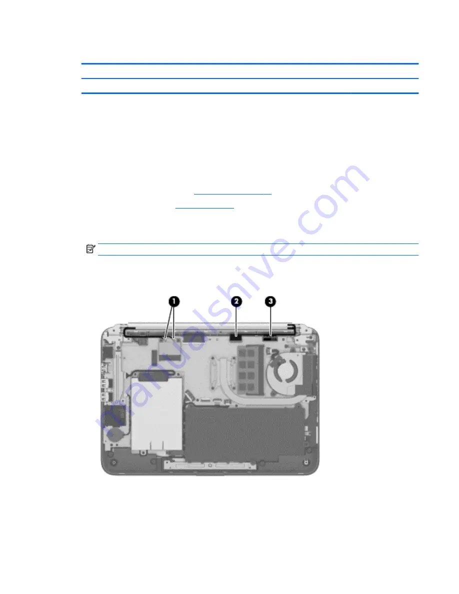
To remove the display assembly:

1.

Release the wireless antenna cables from the clips 

(1)

 built into the base enclosure.

NOTE:

The number of antenna cables may vary.

2.

Disconnect the webcam cable 

(2)

 from the system board.

3.

Disconnect the display panel cable 

(3)

 from the system board.

4.

Lift the black foam piece that covers the right screw on the right hinge 

(1)

.

5.

Remove the two silver Phillips PM2.5×4.0 screws 

(2)

 and the two black Phillips PM2.5×5.0 screws 

(3)

that secure the display assembly and bracket to the computer.

Component replacement procedures

53

Содержание x360 310 G1 PC

Страница 1: ...HP x360 310 G1 PC Maintenance and Service Guide IMPORTANT This document is intended for HP authorized service providers only ...

Страница 2: ...trued as constituting an additional warranty HP shall not be liable for technical or editorial errors or omissions contained herein First Edition December 2014 Document Part Number 803404 001 Product notice This guide describes features that are common to most models Some features may not be available on your computer Not all features are available on all editions of Windows 8 This computer may re...

Страница 3: ...w another hard surface such as an adjoining optional printer or a soft surface such as pillows or rugs or clothing to block airflow Also do not allow the AC adapter to contact the skin or a soft surface such as pillows or rugs or clothing during operation The device and the AC adapter comply with the user accessible surface temperature limits defined by the International Standard for Safety of Inf...

Страница 4: ...iv Safety warning notice ...

Страница 5: ...ag 12 PCID label 13 3 Illustrated parts catalog 14 Computer major components 14 Mass storage devices 17 Miscellaneous parts 17 Display assembly subcomponents 18 Sequential part number listing 19 4 Removal and replacement procedures preliminary requirements 22 Tools required 22 Service considerations 22 Plastic parts 22 Cables and connectors 23 Drive handling 23 Grounding guidelines 24 Electrostati...

Страница 6: ...y BIOS 64 Updating the BIOS 64 Determining the BIOS version 64 Downloading a BIOS update 65 Synchronizing a tablet and keyboard select models only 66 7 Using HP PC Hardware Diagnostics UEFI 67 Downloading HP PC Hardware Diagnostics UEFI to a USB device 67 8 Backing up restoring and recovering 69 Creating recovery media and backups 69 Creating HP Recovery media select models only 69 Using Windows t...

Страница 7: ...ard drive specifications 75 10 Statement of memory volatility 76 Nonvolatile memory usage 78 Questions and answers 80 Using HP Sure Start select models only 81 11 Power cord set requirements 82 Requirements for all countries 82 Requirements for specific countries and regions 82 12 Recycling 84 Index 85 vii ...

Страница 8: ...viii ...

Страница 9: ...mm Supports low voltage differential signaling LVDS co layout with eDP1 3 PSR Memory One customer accessible upgradable memory module slot Support for DDR3L 1333 MHz DDR3L 1600 MHz downgrade to DDR3L 1333 MHz for use with Pentium processors Support for DDR3L 1066 MHz DDR3L 1600 MHz downgrade to DDR3L 1066 MHz for use with Celeron processors Support for 8192 MB of system RAM in the following config...

Страница 10: ...One half size mini card slot support for WLAN Ports AC adapter HP Smart pin plug 4 5 mm barrel Audio one combo audio out headphone audio in microphone jack supports jack auto detection HDMI v 1 4 supporting up to 1080p 1920 1080 at 60 Hz RJ 45 Ethernet 1 USB 3 0 on right side 2 USB 2 0 on left and right sides Video VGA Dsub 15 pin supporting 1920 1200 external resolution at 60 Hz hot plug unplug a...

Страница 11: ...lot TPM Trusted Platform Module Operating system Preinstalled Windows 8 1 Professional 64 Windows 8 1 Small Screen Touch Windows 8 1 Professional Education 64 Windows 8 1 Core for Higher Education ML 64 Web support Windows 8 1 64 Serviceability End user replaceable parts AC adapter 3 ...

Страница 12: ...d it until it pops out 4 USB 2 0 port Connects an optional USB device such as a keyboard mouse external drive printer scanner or USB hub 5 USB 3 0 port Connects an optional USB device such as a keyboard mouse external drive printer scanner or USB hub 6 HDMI port Connects an optional video or audio device such as a high definition television any compatible digital or audio component or a high speed...

Страница 13: ...omputer To learn more about your power settings see your power options From the Start screen type power select Power and sleep settings and then select Power and sleep from the list of applications 3 Power light On The computer is on Blinking The computer is in the Sleep state a power saving state The computer shuts off power to the display and other unneeded components Off The computer is off or ...

Страница 14: ...P Support Assistant app or From the Windows desktop click the question mark icon in the notification area at the far right of the taskbar NOTE When a device is connected to the jack the computer speakers are disabled NOTE Be sure that the device cable has a 4 conductor connector that supports both audio out headphone and audio in microphone 7 Volume button Controls speaker volume To decrease speak...

Страница 15: ... area networks WLANs 5 Internal display switch Turns off the display and initiates Sleep if the display is closed while the power is on NOTE The internal display switch is not visible from the outside of the computer The antennas are not visible from the outside of the computer For optimal transmission keep the areas immediately around the antennas free from obstructions For wireless regulatory no...

Страница 16: ...an entertainment stand To change your notebook to an entertainment stand raise the display and then rotate the display backward to a stand position about 315 degrees Changing your notebook to a tablet To change your notebook to a tablet raise the display and then rotate the display backward until it is flush with the computer bottom 360 degrees 8 Chapter 2 External component identification ...

Страница 17: ...gestures to move the pointer or activate items on the screen NOTE The TouchPad also supports edge swipe gestures 2 Left TouchPad button Functions like the left button on an external mouse 3 Right TouchPad button Functions like the right button on an external mouse Top 9 ...

Страница 18: ...nent Description 1 Caps lock light On Caps lock is on which switches the keys to all capital letters 2 Mute light Amber Computer sound is off Off Computer sound is on 10 Chapter 2 External component identification ...

Страница 19: ...tion with the esc key or on select models the b key or the spacebar 3 Windows key Returns you to the Start screen from an open app or the Windows desktop NOTE Pressing the Windows key again will return you to the previous screen 4 Action keys Execute frequently used system functions NOTE On select models the f5 action key turns the radiance backlight keybard feature off or on Top 11 ...

Страница 20: ...Part number Product number p n 2 This number provides specific information about the product s hardware components The part number helps a service technician to determine what components and parts are needed Model Warranty period 3 Model is the alphanumeric identifier used to locate documents drivers and support for the computer Warranty describes the duration in years of the warranty period for t...

Страница 21: ...reset the notebook firmware BIOS back to factory shipped specifications when replacing the system board The label may have a different number of characters depending on the operating system on the computer Windows 8 models Non Windows 8 models Service tag and PCID label 13 ...

Страница 22: ... continually improves and changes product parts For complete and current information on supported parts for your computer go to http partsurfer hp com select your country or region and then follow the on screen instructions 14 Chapter 3 Illustrated parts catalog ...

Страница 23: ... operating system on models with a 2 cell battery 793104 601 Intel Pentium N3540 processor and the Windows 8 1 Standard operating system on models with a 2 cell battery 793104 501 Intel Pentium N3540 processor and a non Windows 8 1 operating system on models with a 2 cell battery 793104 001 Intel Pentium N3530 processor and the Windows 8 1 Professional operating system on models with a 3 cell batt...

Страница 24: ...Pentium N2830 processor and a non Windows 8 1 operating system on models with a 2 cell battery 774997 001 7 Speaker Kit includes left and right speakers and cable 755738 001 8 RTC battery includes cable 755735 001 9 Heat sink includes replacement thermal material 755728 001 10 Fan 755729 001 11 Power button board includes cable 755733 001 12 Hard drive does not include hard drive bracket hard driv...

Страница 25: ... SSD 7 0 mm 732000 005 500 GB 5400 rpm 7 0 mm 683802 005 Hard Drive Hardware Kit includes hard drive bracket connector cable and screws 755740 001 Solid State Drives 256 GB solid state drive SSD M 2 788297 001 128 GB solid state drive SSD M 2 TLC 777774 001 Miscellaneous parts Component Spare part number AC adapter 45 W HP Smart AC adapter non PFC 4 5 mm non slim 741727 001 Power cord 3 pin black ...

Страница 26: ... enclosure Silver models 758845 001 Red models 758846 001 2 Display cable 761350 001 3 Webcam 758848 001 4 Display hinge covers For use in red models 758847 001 For use in silver models 759503 001 Sensor board not illustrated 788218 001 18 Chapter 3 Illustrated parts catalog ...

Страница 27: ...e hard drive bracket hard drive connector cable and screws are included in the Hard Drive Hardware Kit spare part number 755740 001 755530 001 A Power cord for use in North America 3 pin black 1 0 m 755530 021 A Power cord for use in the United Kingdom and Singapore 3 pin black 1 0 m 755530 031 A Power cord for use in the United Kingdom and Singapore 3 pin black 1 0 m 755530 AR1 A Power cord for u...

Страница 28: ... for use in models with a 2 cell battery 774996 601 N System board equipped with an Intel Pentium N3530 processor and the Windows 8 1 Professional operating system for use in models with a 2 cell battery 774997 001 N System board equipped with an Intel Pentium N2830 processor and a non Windows 8 1 operating system for use in models with a 2 cell battery 774997 501 N System board equipped with an I...

Страница 29: ...N2840 processor and the Windows 8 1 Standard operating system for use in models with a 2 cell battery 793105 601 N System board equipped with an Intel Pentium N2840 processor and the Windows 8 1 Professional operating system for use in models with a 2 cell battery 794721 001 N System board equipped with an Intel Pentium N3540 processor and a non Windows 8 1 operating system for use in models with ...

Страница 30: ...rations that you must keep in mind during disassembly and assembly procedures NOTE As you remove each subassembly from the computer place the subassembly and all accompanying screws away from the work area to prevent damage Plastic parts CAUTION Using excessive force during disassembly and reassembly can damage plastic parts Use care when handling the plastic parts Apply pressure only at the point...

Страница 31: ...or inserting a hard drive shut down the computer If you are unsure whether the computer is off or in Hibernation turn the computer on and then shut it down through the operating system Before handling a drive be sure that you are discharged of static electricity While handling a drive avoid touching the connector Before removing a diskette drive or optical drive be sure that a diskette or disc is ...

Страница 32: ... components in their electrostatic safe containers until you are ready to install them Before touching an electronic component discharge static electricity by using the guidelines described in this section Avoid touching pins leads and circuitry Handle electronic components as little as possible If you remove a component place it in an electrostatic safe container The following table shows how hum...

Страница 33: ... to ground and that proper materials are selected to avoid static charging When grounding is not possible use an ionizer to dissipate electric charges Workstation guidelines Follow these grounding workstation guidelines Cover the workstation with approved static shielding material Use a wrist strap connected to a properly grounded work surface and use properly grounded tools and equipment Use cond...

Страница 34: ...operator and ground To be effective the conductive must be worn in contact with the skin The following grounding equipment is recommended to prevent electrostatic damage Antistatic tape Antistatic smocks aprons and sleeve protectors Conductive bins and other assembly or soldering aids Nonconductive foam Conductive tabletop workstations with ground cords of one megohm resistance Static dissipative ...

Страница 35: ...nd current information on supported parts for your computer go to http partsurfer hp com select your country or region and then follow the on screen instructions Component replacement procedures This chapter provides removal and replacement procedures for Authorized Service Provider only parts There are as many as 76 screws that must be removed replaced and or loosened when servicing the computer ...

Страница 36: ... If you are unsure whether the computer is off or in Hibernation turn the computer on and then shut it down through the operating system 2 Disconnect the power from the computer by unplugging the power cord from the computer 3 Disconnect all external devices from the computer Remove the bottom cover 1 Position the computer upside down 2 Pry the two rear rubber feet off the bottom cover 1 3 Remove ...

Страница 37: ... seam near the display hinges 1 and then lift the cover up and off the computer 2 far enough to access the USB audio board connector on the system board NOTE When you lift the bottom cover a cable is connected from the USB audio board installed on the inside of the bottom cover to the system board Be sure not to pull the cable loose when lifting the bottom cover Component replacement procedures 29...

Страница 38: ...em board by lifting the ZIF connector 1 and then removing the USB audio board cable from the system board connector 2 Reverse this procedure to install the bottom cover 30 Chapter 5 Removal and replacement procedures for Authorized Service Provider parts ...

Страница 39: ... external devices connected to the computer 3 Disconnect the power from the computer by first unplugging the power cord from the AC outlet and then unplugging the AC adapter from the computer 4 Remove the bottom cover see Bottom cover on page 28 To remove the USB audio board 1 Position the bottom cover upside down 2 Remove the Phillips PM2 0 3 0 screw 1 3 Lift up on the rear of the board and lift ...

Страница 40: ...ese steps 1 Turn off the computer If you are unsure whether the computer is off or in Hibernation turn the computer on and then shut it down through the operating system 2 Disconnect the power from the computer by unplugging the power cord from the computer 3 Disconnect all external devices from the computer 4 Remove the bottom cover see Bottom cover on page 28 5 Disconnect the battery Remove the ...

Страница 41: ...e NOTE If the WLAN antenna cables are not connected to the terminals on the WLAN module the protective sleeves must be installed on the antenna connectors as shown in the following illustration Reverse this procedure to install the WLAN module Component replacement procedures 33 ...

Страница 42: ...ugh the operating system 2 Disconnect the power from the computer by unplugging the power cord from the computer 3 Disconnect all external devices from the computer 4 Remove the bottom cover see Bottom cover on page 28 5 Disconnect the battery Remove the solid state drive 1 Remove the Phillips PM2 0 3 5 screw 1 that secures the solid state drive to the system board 2 Remove the solid state drive 2...

Страница 43: ...Reverse this procedure to install the solid state drive Component replacement procedures 35 ...

Страница 44: ...mputer on and then shut it down through the operating system 2 Disconnect the power from the computer by unplugging the power cord from the computer 3 Disconnect all external devices from the computer 4 Remove the bottom cover see Bottom cover on page 28 5 Disconnect the battery Remove the hard drive 1 Disconnect the hard drive connector cable 1 from the system board 2 Remove the Phillips PM2 0 7 ...

Страница 45: ...rd drive perform the following steps a Disconnect the hard drive connector cable 1 from the hard drive b Remove the four Phillips PM3 0 3 0 screws 2 that secure the hard drive bracket to the hard drive c Remove the hard drive bracket 3 from the hard drive The hard drive bracket hard drive connector cable and screws are available in the Hard Drive Hardware Kit spare part number 755740 001 Component...

Страница 46: ...Reverse this procedure to install the hard drive 38 Chapter 5 Removal and replacement procedures for Authorized Service Provider parts ...

Страница 47: ...ation turn the computer on and then shut it down through the operating system 2 Disconnect the power from the computer by unplugging the power cord from the computer 3 Disconnect all external devices from the computer 4 Remove the bottom cover see Bottom cover on page 28 5 Disconnect the battery Remove the RTC battery 1 Disconnect the RTC battery cable 1 from the system board Component replacement...

Страница 48: ...om the system board The RTC battery is secured with double sided tape 3 Remove the RTC battery Reverse this procedure to install the RTC battery 40 Chapter 5 Removal and replacement procedures for Authorized Service Provider parts ...

Страница 49: ...g system and then click Next 6 Under Step 2 Select a Download click the BIOS link 7 Click the link for the most recent BIOS 8 Click the Download button and then follow the on screen instructions Before removing a memory module follow these steps 1 Turn off the computer If you are unsure whether the computer is off or in Hibernation turn the computer on and then shut it down through the operating s...

Страница 50: ... the memory module 2 by pulling the module away from the slot at an angle Reverse this procedure to install a memory module 42 Chapter 5 Removal and replacement procedures for Authorized Service Provider parts ...

Страница 51: ...down through the operating system 2 Disconnect the power from the computer by unplugging the power cord from the computer 3 Disconnect all external devices from the computer 4 Remove the bottom cover see Bottom cover on page 28 5 Disconnect the battery Remove the power button board 1 Disconnect the power button board cable 1 from the system board 2 Remove the two Phillips PM2 0 3 0 screws 2 that s...

Страница 52: ...3 Remove the power button board and cable 3 Reverse this procedure to install the power button board 44 Chapter 5 Removal and replacement procedures for Authorized Service Provider parts ...

Страница 53: ...r 3 Disconnect all external devices from the computer 4 Remove the bottom cover see Bottom cover on page 28 5 Disconnect the battery Remove the fan NOTE You do not have to remove the heat sink to remove the fan You must disengage the tape that secures the fan to the heat sink 1 Disconnect the fan cable 1 from the system board 2 Remove the two Phillips PM2 0 3 0 screws 2 that secure the fan to the ...

Страница 54: ...ther the computer is off or in Hibernation turn the computer on and then shut it down through the operating system 2 Disconnect the power from the computer by unplugging the power cord from the computer 3 Disconnect all external devices from the computer 4 Remove the bottom cover see Bottom cover on page 28 5 Disconnect the battery 6 Remove the fan see Fan on page 45 46 Chapter 5 Removal and repla...

Страница 55: ...t secures the heat sink to the fan 3 Remove the heat sink 3 NOTE Due to the adhesive quality of the thermal material located between the heat sink and the system board components it may be necessary to move the heat sink from side to side to detach it NOTE The thermal material must be thoroughly cleaned from the surfaces of the heat sink and the system board components each time the heat sink is r...

Страница 56: ...Reverse this procedure to install the heat sink 48 Chapter 5 Removal and replacement procedures for Authorized Service Provider parts ...

Страница 57: ... unplugging the power cord from the computer 3 Disconnect all external devices from the computer 4 Remove the bottom cover see Bottom cover on page 28 Remove the battery WARNING To reduce potential safety issues use only the battery provided with the computer a replacement battery provided by HP or a compatible battery purchased from HP 1 Disconnect the battery cable from the system board 1 2 Remo...

Страница 58: ...Disconnect all external devices from the computer 4 Remove the bottom cover see Bottom cover on page 28 5 Remove the battery see Battery on page 49 Remove the speakers 1 Disconnect the speaker cable from the system board 1 2 Remove the four Phillips PM2 0 6 0 broadhead screws 2 that secure the speakers to the computer NOTE Make note of the rubber gaskets 3 that fit around each screw For installati...

Страница 59: ...3 Disconnect all external devices from the computer 4 Remove the bottom cover see Bottom cover on page 28 5 Remove the battery see Battery on page 49 Remove the TouchPad button board 1 Disconnect the TouchPad board cable from the system board 1 2 Remove the two Phillips PM2 0 3 0 screws 2 that secure the bracket and then rotate the front of the bracket up and lift it off the computer 4 3 Remove th...

Страница 60: ...bottom of the touchpad upward 2 and then lift it off the computer 3 Reverse this procedure to install the TouchPad button board 52 Chapter 5 Removal and replacement procedures for Authorized Service Provider parts ...

Страница 61: ...he AC outlet and then unplugging the AC adapter from the computer 4 Remove the bottom cover see Bottom cover on page 28 5 Remove the battery see Battery on page 49 To remove the display assembly 1 Release the wireless antenna cables from the clips 1 built into the base enclosure NOTE The number of antenna cables may vary 2 Disconnect the webcam cable 2 from the system board 3 Disconnect the displa...

Страница 62: ...y from the computer 5 If it is necessary to replace any of the display assembly subcomponents 1 To remove the display enclosure NOTE The display enclosure is available using the following spare part numbers 758846 001 for use in red models 758845 001 for use in silver models a Remove the two screw covers 1 b Remove the two Phillips PM2 5 4 0 screws 2 that secure the enclosure to the display 54 Cha...

Страница 63: ... To remove the webcam module NOTE The webcam is available using spare part number 758848 001 a Lift the webcam module 1 enough to gain access to the cable b Disconnect the cable 2 from the module 3 To remove the display hinge covers Component replacement procedures 55 ...

Страница 64: ...cover to the display c Remove the bottom display hinge cover from the display 3 4 To remove the display cable NOTE The display cable is available using spare part number 761350 001 a Disconnect the end of the display cable from the small connector at the bottom of the display panel 1 b Disconnect the display cable from the large connector on the bottom of the display panel 2 56 Chapter 5 Removal a...

Страница 65: ...e sensor board NOTE The sensor board is available using spare part number 788218 001 a Disconnect the cable from the board 1 b Remove the Phillips PM2 0 3 0 screw that secures the board to the display enclosure 2 c Remove the sensor board from the display 3 Reverse this procedure to reassemble and install the display assembly Component replacement procedures 57 ...

Страница 66: ...r see Bottom cover on page 28 5 Remove the battery see Battery on page 49 Remove the power connector cable 1 Remove the black Phillips PM2 5 6 0 screw 1 that secures the bracket to the computer and the silver Phillips PM3 0 5 0 screw 2 that secures the right display hinge 2 Open the display assembly right hinge 3 as far as it will open 3 Remove the bracket from the computer 4 4 Disconnect the powe...

Страница 67: ... 501 Intel Pentium N3530 processor and a non Windows 8 1 operating system on models with a 2 cell battery 774996 001 Intel Pentium N2840 processor and the Windows 8 1 Professional operating system on models with a 3 cell battery 794722 601 Intel Pentium N2840 processor and the Windows 8 1 Standard operating system on models with a 3 cell battery 794722 501 Intel Pentium N2840 processor and a non W...

Страница 68: ...at sink on page 46 Fan see Fan on page 45 Remove the system board 1 Disconnect the following cables from the system board 1 Power connector cable 2 Wireless antennas may include one or two antennas 3 Keyboard cable 4 Webcam cable 5 Display cable 6 Power button board cable 7 Fan cable 8 Speaker cable 9 Touchpad board cable 10 Hard drive cable 2 Remove the four Phillips PM2 0 3 0 screws 1 that secur...

Страница 69: ...3 Remove the system board 2 from the computer Reverse this procedure to install the system board Component replacement procedures 61 ...

Страница 70: ...u are unsure whether the computer is off or in Hibernation turn the computer on and then shut it down through the operating system 2 Disconnect the power from the computer by unplugging the power cord from the computer 3 Disconnect all external devices from the computer 4 Remove the bottom cover see Bottom cover on page 28 5 Remove the hard drive see Hard drive on page 36 6 Remove the fan see Fan ...

Страница 71: ...yboard from the top cover Top covers are available using spare part number 790943 001 for red models and 781865 001 for silver models Reverse this procedure to install the keyboard Component replacement procedures 63 ...

Страница 72: ...estart the tablet and then quickly hold down the Windows button 2 Tap f10 Updating the BIOS Updated versions of the BIOS may be available on the HP website Most BIOS updates on the HP website are packaged in compressed files called SoftPaqs Some download packages contain a file named Readme txt which contains information regarding installing and troubleshooting the file Determining the BIOS versio...

Страница 73: ...date and compare it to the BIOS version currently installed on your computer If the update is more recent than your BIOS make a note of the date name or other identifier You may need this information to locate the update later after it has been downloaded to your hard drive b Follow the on screen instructions to download your selection to the hard drive If the update is more recent than your BIOS ...

Страница 74: ...to be synchronized If so BIOS will start the synchronization If the synchronization is interrupted a notification screen displays for 10 seconds before the tablet restarts and attempts to synchronize again NOTE The Embedded Controller firmware will synchronize ONLY if the tablet or keyboard battery is more than 50 charged or if your tablet is connected to AC power 66 Chapter 6 Using Setup Utility ...

Страница 75: ...board arrow keys to select the type of diagnostic test you want to run and then follow the on screen instructions NOTE If you need to stop a diagnostic test press or tap esc NOTE To start the Setup Utility your computer must be in notebook mode and you must use the keyboard attached to your notebook The on screen keyboard which displays in tablet mode cannot access the Setup Utility Downloading HP...

Страница 76: ...Find Now to let HP automatically detect your product 4 Select your computer model and then select your operating system 5 In the Diagnostic section click HP UEFI Support Environment or Click Download and then select Run 68 Chapter 7 Using HP PC Hardware Diagnostics UEFI ...

Страница 77: ...mation on creating recovery media see Creating HP Recovery media select models only on page 69 For information on the recovery options that are available using the recovery media see Recovering using HP Recovery Manager on page 71 Use Windows tools to create system restore points and create backups of personal information For more information see Using Windows tools on page 70 NOTE If storage is 3...

Страница 78: ...ce such as a USB hub Be sure that the computer is connected to AC power before you begin creating the recovery media The creation process can take an hour or more Do not interrupt the creation process If necessary you can exit the program before you have finished creating all of the recovery DVDs HP Recovery Manager will finish burning the current DVD The next time you start HP Recovery Manager yo...

Страница 79: ...rmation see Recovering using HP Recovery Manager on page 71 If you have not already created recovery media see Creating HP Recovery media select models only on page 69 On select models if you want to recover the computer s original factory partition and content or if you have replaced the hard drive you can use the Factory Reset option of HP Recovery media For more information see Recovering using...

Страница 80: ...ory Reset Restores the computer to its original factory state by deleting all information from the hard drive and re creating the partitions Then it reinstalls the operating system and the software that was installed at the factory The HP Recovery partition select models only allows System Recovery and Minimized Image Recovery select models only Using the HP Recovery partition select models only T...

Страница 81: ...ers or tablets without keyboards attached Turn on or restart the computer quickly press the volume down button and then tap f9 for boot options or Turn on or restart the computer quickly press the Windows button and then tap f9 for boot options 3 Select the optical drive or USB flash drive from which you want to boot 4 Follow the on screen instructions Removing the HP Recovery partition select mod...

Страница 82: ...ting 5 C to 35 C 41 F to 95 F Nonoperating 20 C to 60 C 4 F to 140 F Relative humidity noncondensing Operating 10 to 90 Nonoperating 5 to 95 Maximum altitude unpressurized Operating 15 m to 3 048 m 50 ft to 10 000 ft Nonoperating 15 m to 12 192 m 50 ft to 40 000 ft NOTE Applicable product safety standards specify thermal limits for plastic surfaces The device operates well within this range of tem...

Страница 83: ...times typical read including setting Single track 1 1 ms 1 5 ms 1 5 ms Average read write 11 ms 11 13 ms 11 13 ms Maximum 18 ms 22 ms 22 ms Logical blocks 1 285 971 976 773 168 628 142 448 Disk rotational speed 5400 rpm 5400 rpm 5400 rpm Operating temperature 0 C to 60 C 32 F to 140 F 0 C to 60 C 32 F to 140 F 0 C to 60 C 32 F to 140 F 1 GB 1 billion bytes when referring to hard drive storage capa...

Страница 84: ...ecommended a Turn on or restart the computer and then press esc while the Press the ESC key for Startup Menu message is displayed at the bottom of the screen NOTE If the system has a BIOS administrator password enter the password at the prompt b Select Main select Restore Defaults and then select Yes to load defaults c Select the Security menu select Restore Security Level Defaults and then select...

Страница 85: ...the bottom of the screen b Select the Security menu and scroll down to the Utilities menu c Select Hard Drive Tools d Under Utilities select Secure Erase select the hard drive storing the data you want to clear and then follow the on screen instructions to continue or Clear the contents of the drive by using the following Disk Sanitizer command steps IMPORTANT If you clear data using Disk Sanitize...

Страница 86: ...t customer accessible No Yes Stores NIC configuration and NIC firmware NIC EEPROM is programmed using a utility from the NIC vendor that can be run from DOS A utility is required to write data to this memory and is available from the NIC vendor Writing data to this ROM in an inappropriate manner will render the NIC non functional DIMM Serial Presence Detect SPD configuration data 256 Bytes per mem...

Страница 87: ...mware updates digitally signed by Intel can be applied using this utility Bluetooth flash 2 Mbit No Yes Stores Bluetooth configuration and firmware Bluetooth flash is programmed at the factory Tools for writing data to this memory are not publicly available but can be obtained from the silicon vendor A utility is required for writing data to this memory and is made available through newer versions...

Страница 88: ...m diagnostics The UEFI BIOS provides functionality beyond that of the legacy BIOS In addition the UEFI BIOS works to initialize the computer s hardware before loading and executing the OS the run time environment allows the loading and execution of software programs from storage devices to provide more functionality such as advanced hardware diagnostics with the ability to display more detailed sy...

Страница 89: ... Turn on or restart the computer and then press esc while the Press the ESC key for Startup Menu message is displayed at the bottom of the screen b Select the Security menu select Secure Boot Configuration and then follow the on screen instructions c At the Secure Boot Configuration window select Secure Boot select Clear Secure Boot Keys and then follow the on screen instructions to continue Using...

Страница 90: ...roved by an acceptable accredited agency responsible for evaluation in the country or region where the power cord set will be used The power cord sets must have a minimum current capacity of 10 amps and a nominal voltage rating of 125 or 250 V AC as required by the power system of each country or region The appliance coupler must meet the mechanical configuration of an EN 60 320 IEC 320 Standard S...

Страница 91: ...ord and wall plug must bear a T mark and registration number in accordance with the Japanese Dentori Law The flexible cord must be Type VCT or VCTF 3 conductor 1 00 mm conductor size The wall plug must be a two pole grounding type with a Japanese Industrial Standard C8303 7 A 125 V configuration 4 The flexible cord must be Type RVV 3 conductor 0 75 mm conductor size Power cord set fittings applian...

Страница 92: ...in general household waste Follow the local laws and regulations in your area for battery disposal HP encourages customers to recycle used electronic hardware HP original print cartridges and rechargeable batteries For more information about recycling programs see the HP Web site at http www hp com recycle 84 Chapter 12 Recycling ...

Страница 93: ...mber 18 display hinge spare part number 18 display hinge cover spare part number 20 display hinge covers removing 55 display hinge covers spare part number 18 display panel product description 1 display rear cover spare part number 20 drives preventing damage 23 DVD RW Double Layer with SuperMulti Drive precautions 23 E electrostatic discharge 24 equipment guidelines 26 esc key identifying 11 Ethe...

Страница 94: ...tic parts service considerations 22 ports HDMI 4 product description 2 USB 2 0 4 5 USB 3 0 4 power button board removal 43 spare part number 16 19 43 power button identifying 5 power connector cable removal 58 spare part number 15 19 58 power connector identifying 4 power cord set requirements 82 spare part numbers 19 power lights identifying 5 power requirements product description 2 processor pr...

Страница 95: ... system memory removing personal data from volatile 76 system recovery 71 system restore point creating 70 system restore point creating 69 T tools required 22 TouchPad buttons 9 TouchPad button board removal 51 TouchPad zone identifying 9 transporting guidelines 25 U USB 2 0 ports identifying 4 5 USB 3 0 ports identifying 4 USB audio board removing 31 spare part number 17 19 31 V vents identifyin...

Отзывы: