
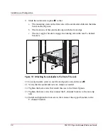
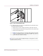

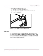
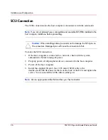


Installation and Configuration
40
SSL1016 Tape Autoloader Reference Guide
Verification
When you first power on the autoloader, it automatically runs a Power On Self
Test (POST). During the POST, the right (amber) LED flashes rapidly. After the
POST, the left (green) LED illuminates steadily, and after approximately three
minutes the LCD displays the HP logo and drive type. Do one of the following:
■
If the autoloader powers on successfully, continue configuring the autoloader.
See “Configuration.”
■
If the autoloader does not power on successfully, make sure that:
— The rear power switch is on.
— The power cord is inserted correctly.
— The SCSI bus is terminated.
— The SCSI cable is connected to the autoloader and host computer.
— The On/Off button on the front of the autoloader has been pressed.
— There is not an error code displayed on the autoloader’s LCD. (If an error
message is displayed, see Chapter 6, “Troubleshooting.”)
If you cannot resolve the problem yourself, contact your authorized service
representative.
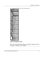
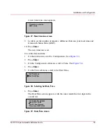
Configuration
To configure your autoloader, use the Configuration submenu on the front panel.
When you first power on the autoloader, it defaults to no password protection.
After you set the security option, however, all the configuration functionality is
password-protected; you need an administrator-level password to configure the
autoloader.
Содержание StorageWorks SSL1016
Страница 8: ...Contents 8 SSL1016 Tape Autoloader Reference Guide ...
Страница 14: ...About this Guide 14 SSL1016 Tape Autoloader Reference Guide ...
Страница 22: ...Overview 22 SSL1016 Tape Autoloader Reference Guide ...
Страница 60: ...Installation and Configuration 60 SSL1016 Tape Autoloader Reference Guide ...
Страница 102: ...Autoloader Operation 102 SSL1016 Tape Autoloader Reference Guide Figure 78 Moving tapes using Web Administration ...
Страница 118: ...Autoloader Operation 118 SSL1016 Tape Autoloader Reference Guide ...
Страница 126: ...Tape Drive Cleaning 126 SSL1016 Tape Autoloader Reference Guide ...
Страница 143: ...Regulatory Compliance Notices 143 SSL1016 Tape Autoloader Reference Guide Japanese Notice ...
Страница 144: ...Regulatory Compliance Notices 144 SSL1016 Tape Autoloader Reference Guide ...
Страница 154: ...Upgrading or Replacing the DCA 154 SSL1016 Tape Autoloader Reference Guide Figure 92 Bottom of DCA ...
Страница 156: ...Upgrading or Replacing the DCA 156 SSL1016 Tape Autoloader Reference Guide ...
Страница 160: ...Index 160 SSL1016 Tape Autoloader Reference Guide ...