


78 Troubleshooting
LED Status Indications
If a component fails in an enclosure, the fault will be indicated by at least two
amber fault LEDs. For example, if a disk drive fails, the system fault LED will
light and the disk drive fault LED will light.
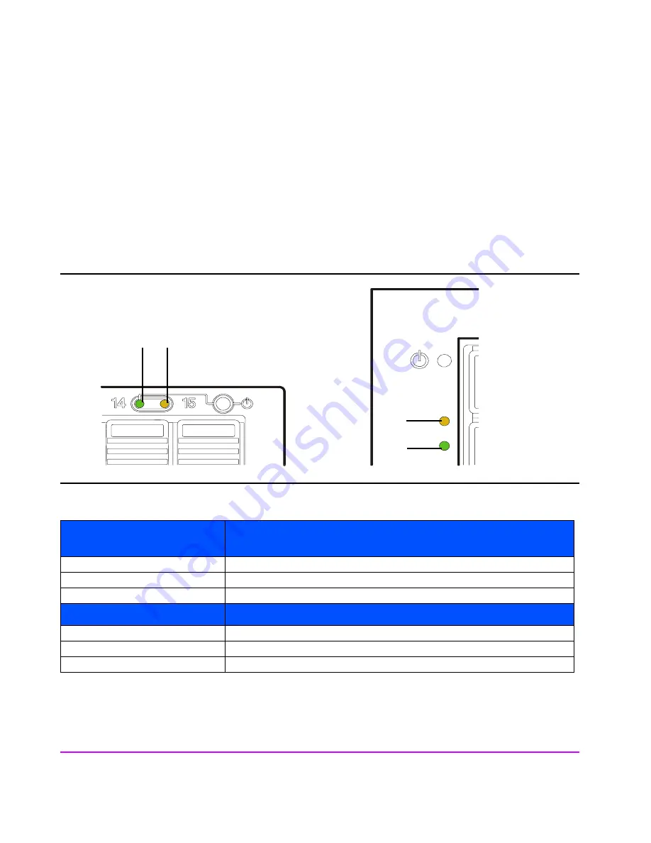
The status LEDs for the various hardware assemblies are shown in Figure 24
through Figure 31. The status indications are described in the accompanying
tables.
Figure 24
System LEDs
Table 6
System LEDs Status Indications (See Figure 24)
*States can occur simultaneously with Amber(**) states.
**States can occur simultaneously with Green(*) states.
A System Power/
Activity (Green)
Indication
Off*
ANDed with Amber On or Amber Flashing
or
enclosure not under power.
On
Enclosure under power; no I/O activity.
Flashing*
I/O activity.
B System Fault (Amber)
Off
Enclosure not under power
or
no active warning.
On**
Warning active (FRU fault).
Flashing**
Host is identifying a FRU.
A
B
B
A
Rackmount enclosure
VA 7100 Desk Side
Содержание StorageWorks 7110 - Virtual Array
Страница 12: ...12 Contents ...
Страница 54: ...54 Product Overview Figure 21 VA 7110 I O Architecture ...
Страница 90: ...90 Troubleshooting ...
Страница 113: ...Servicing Upgrading 113 Servicing Upgrading Figure 43 Removing Installing a VA 7100 Controller 1 2 3 4 ...
Страница 114: ...114 Servicing Upgrading Figure 44 Removing Installing a VA 7110 7400 7410 Array Controller 1 2 3 ...
Страница 116: ...116 Servicing Upgrading Figure 45 Removing Installing an Array Controller Filler Panel 1 2 3 ...
Страница 119: ...Servicing Upgrading 119 Servicing Upgrading Figure 47 Connecting an Array Controller Battery 1 3 4 5 2 ...
Страница 124: ...124 Servicing Upgrading Figure 49 Removing Installing a Midplane Assembly 2 1 4 5 8 7 9 10 6 3 ...
Страница 129: ...Servicing Upgrading 129 Servicing Upgrading Figure 52 Removing and Installing an LCC 1 2 3 ...
Страница 130: ...130 Servicing Upgrading Figure 53 Setting the FC Loop Speed Switch Must be set to 1GB s ...
Страница 149: ...Specifications Regulatory Statements 149 Specifications Regulatory Statements ...
Страница 151: ...Specifications Regulatory Statements 151 Specifications Regulatory Statements ...
Страница 152: ...152 Specifications Regulatory Statements ...
Страница 164: ...164 Index ...