


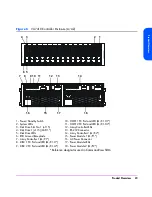


28 Product Overview
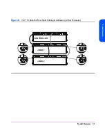
If an image disk fails on the VA 7100 or VA 7400, the array will operate with
a single image disk until the failed disk is replaced. If an image disk fails on
the VA 7410, the backup image disk will be used, maintaining image disk
redundancy. When the original failed image disk is replaced, it will be
assigned the role of backup image disk.
Disk Drive Filler Panels
Disk drive filler panels are used in both the controller and disk enclosures to fill
empty slots in place of disk drives. A filler panel must be installed to maintain
proper cooling in the enclosure.
Caution
Do not operate the array for more than 5 minutes with a disk
drive or filler panel removed. Either a disk drive or filler panel
must be installed in the slot to maintain proper airflow and avoid
overheating.
Power Modules
The controller enclosure is shipped with two fully redundant power modules.
Each power module contains:
■
An autoranging power supply that converts ac input power to dc output
power for use by the other array components. The power supplies share the
power load under non-fault conditions. If one power supply fails, the other
supply delivers the entire load to maintain power for the array. Each power
supply uses a separate power cord. Both power supplies can be plugged
into a common ac power source, or each supply can be plugged into a
separate ac circuit to provide power source redundancy.
■
Two internal blowers, which provide airflow and maintain the proper
operating temperature within the enclosure. If a blower fails, a fault will
occur. The other power module will continue to operate and its blowers will
continue to cool the enclosure. Even if a power supply fails, both of the
blowers within the power module will continue to operate; dc power for the
blowers is distributed from the midplane.
Содержание StorageWorks 7110 - Virtual Array
Страница 12: ...12 Contents ...
Страница 54: ...54 Product Overview Figure 21 VA 7110 I O Architecture ...
Страница 90: ...90 Troubleshooting ...
Страница 113: ...Servicing Upgrading 113 Servicing Upgrading Figure 43 Removing Installing a VA 7100 Controller 1 2 3 4 ...
Страница 114: ...114 Servicing Upgrading Figure 44 Removing Installing a VA 7110 7400 7410 Array Controller 1 2 3 ...
Страница 116: ...116 Servicing Upgrading Figure 45 Removing Installing an Array Controller Filler Panel 1 2 3 ...
Страница 119: ...Servicing Upgrading 119 Servicing Upgrading Figure 47 Connecting an Array Controller Battery 1 3 4 5 2 ...
Страница 124: ...124 Servicing Upgrading Figure 49 Removing Installing a Midplane Assembly 2 1 4 5 8 7 9 10 6 3 ...
Страница 129: ...Servicing Upgrading 129 Servicing Upgrading Figure 52 Removing and Installing an LCC 1 2 3 ...
Страница 130: ...130 Servicing Upgrading Figure 53 Setting the FC Loop Speed Switch Must be set to 1GB s ...
Страница 149: ...Specifications Regulatory Statements 149 Specifications Regulatory Statements ...
Страница 151: ...Specifications Regulatory Statements 151 Specifications Regulatory Statements ...
Страница 152: ...152 Specifications Regulatory Statements ...
Страница 164: ...164 Index ...