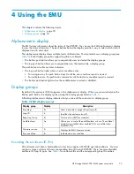
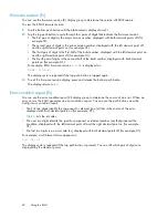


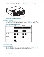

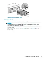

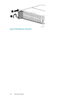

LEDs on the rear of the enclosure indicate the status of the EMU, I/O modules, and power supply/blower
assemblies. Operational states of the LEDs are shown in
Figure 26
.
CXO7959A
Figure 26 LEDs in the operational state
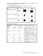
Audible error indicators
If enabled, the audible alarm sounds when the EMU detects an error. The sound pattern identi
fi
es the
error severity.
Table 9
shows the duration of the different alarms. See "
Audible alarm
" on page 41 for
instructions to control the alarm.
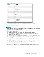
Table 9 Audible alarm sound patterns
Error severity
Cycle 1
Cycle 2
Unrecoverable
Critical
Noncritical
Information
Legend
Alarm on
Alarm off
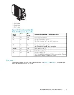
Visual error indicators
I/O module and transceivers
LEDs on the I/O module report the status of transceiver signals and I/O module power. Use
Figure 27
and
Table 10
to interpret the I/O module errors and determine what action to take.
50
Troubleshooting
Содержание StorageWorks 2500
Страница 1: ...HP StorageWorks 2500 Disk System user guide Part number 5697 6800 Second edition June 2007 ...
Страница 8: ...8 ...
Страница 12: ...12 About this guide ...
Страница 44: ...44 Using the EMU ...
Страница 54: ...54 Troubleshooting ...
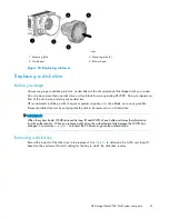
Страница 64: ...Figure 35 Replacing a disk drive 64 Customer self repair ...
Страница 68: ...68 Specifications ...
Страница 78: ...78 Regulatory notices ...
Страница 88: ...88 EMU generated error condition reports ...


