background image

2

Installing and Customizing the
Software

If your computer was not shipped with a Microsoft operating system, some portions of this
documentation do not apply. Additional information is available in online help after you install the
operating system.

NOTE:

If the computer was shipped with Windows Vista or Windows 7 loaded, you will be prompted

to register the computer with HP Total Care before installing the operating system. You will see a
brief movie followed by an online registration form. Fill out the form, click the 

Begin

 button, and follow

the instructions on the screen.

CAUTION:

Do not add optional hardware or third-party devices to the computer until the operating

system is successfully installed. Doing so may cause errors and prevent the operating system from
installing properly.

NOTE:

Be sure there is a 10.2-cm (4-inch) clearance at the back of the unit and above the monitor

to permit the required airflow.

Installing the Operating System

The first time you turn on the computer, the operating system is installed automatically. This process
takes about 5 to 10 minutes, depending on which operating system is being installed. Carefully read
and follow the instructions on the screen to complete the installation.

CAUTION:

Once the automatic installation has begun, DO NOT TURN OFF THE COMPUTER

UNTIL THE PROCESS IS COMPLETE. Turning off the computer during the installation process may
damage the software that runs the computer or prevent its proper installation.

NOTE:

If the computer shipped with more than one operating system language on the hard drive,

the installation process could take up to 60 minutes.

If your computer was not shipped with a Microsoft operating system, some portions of this
documentation do not apply. Additional information is available in online help after you install the
operating system.

Downloading Microsoft Windows Updates

1.

To set up your Internet connection, click 

Start

 > 

Internet Explorer

 and follow the instructions on

the screen.

2.

Once an Internet connection has been established, click the 

Start

 button.

4

Chapter 2   Installing and Customizing the Software

Содержание Pro 1005

Страница 1: ...Maintenance Service Guide HP Pro 1005 All in One Business PC ...

Страница 2: ...ch products and services Nothing herein should be construed as constituting an additional warranty HP shall not be liable for technical or editorial errors or omissions contained herein This document contains proprietary information that is protected by copyright No part of this document may be photocopied reproduced or translated to another language without the prior written consent of Hewlett Pa...

Страница 3: ...ollow directions could result in bodily harm or loss of life CAUTION Text set off in this manner indicates that failure to follow directions could result in damage to equipment or loss of information NOTE Text set off in this manner provides important supplemental information iii ...

Страница 4: ...iv About This Book ...

Страница 5: ...the Software 5 3 Computer Setup F10 Utility 6 Computer Setup F10 Utilities 6 Using Computer Setup F10 Utilities 7 Computer Setup File 7 Computer Setup Storage 9 Computer Setup Security 11 Computer Setup Power 14 Computer Setup Advanced 15 4 Serial ATA SATA Drive Guidelines and Features 17 SATA Hard Drives 17 SATA Hard Drive Cables 17 SATA Data Cable 17 SMART ATA Drives 18 Hard Drive Capacities 18 ...

Страница 6: ...Screws 24 Cables and Connectors 25 Hard Drives 25 Lithium Coin Cell Battery 25 6 Illustrated parts catalog 27 Computer major components 27 Cables 28 Boards 29 Misc Parts 30 Mass storage devices not illustrated 31 Power cords not illustrated 31 Sequential part number listing 31 7 Removal and Replacement Procedures All in One AIO Chassis 34 Preparing to Disassemble the Computer 34 Rear Cover 35 Stan...

Страница 7: ...s 91 Solving Printer Problems 93 Solving Keyboard and Mouse Problems 94 Solving Hardware Installation Problems 96 Solving Network Problems 97 Solving Memory Problems 101 Solving Processor Problems 102 Solving CD ROM and DVD Problems 103 Solving USB Flash Drive Problems 105 Solving Front Panel Component Problems 106 Solving Internet Access Problems 106 Solving Software Problems 109 Contacting Custo...

Страница 8: ... 123 Line out Audio 123 Appendix D Power Cord Set Requirements 124 General Requirements 124 Japanese Power Cord Requirements 124 Country Specific Requirements 125 Appendix E Specifications 126 All in One Models 126 Index 127 viii ...

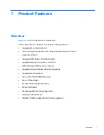
Страница 9: ... Adjustable tilt stand Integrated AMD Radeon HD 6320 Graphics Integrated Network Connection 10 100 NIC AMD E Series E 450 Dual Core processor Integrated low light webcam with dual microphones Integrated stereo speakers Up to 8 GB of DDR3 SDRAM memory Up to 1 TB hard drive HP Slim SATA 8X SuperMulti Drive Media Card Reader HP Wireless NIC 802 11b g n Mini Card USB Keyboard and Mouse ENERGY STAR qua...

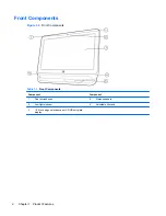
Страница 10: ...Front Components Table 1 1 Front Components Component Component 1 Dual microphones 4 Stereo speakers 2 Low light webcam 5 Adjustable tilt stand 3 18 5 inch diagonal widescreen LCD HD anti glare display 2 Chapter 1 Product Features ...

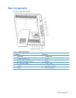
Страница 11: ...mponent Component 1 Power Button 7 Headphone jack 2 LED Indicator HDD activity 8 Line out 3 LED Indicator Card reader activity 9 Ethernet 4 6 in 1 Media Card Reader 10 4 USB 2 0 ports 5 2 USB 2 0 11 DC Power In Connector 6 MIC jack 12 LED Indicator power Rear Components 3 ...

Страница 12: ...em The first time you turn on the computer the operating system is installed automatically This process takes about 5 to 10 minutes depending on which operating system is being installed Carefully read and follow the instructions on the screen to complete the installation CAUTION Once the automatic installation has begun DO NOT TURN OFF THE COMPUTER UNTIL THE PROCESS IS COMPLETE Turning off the co...

Страница 13: ...n with C i386 or use the Browse button in the dialog box to locate the i386 folder This action points the operating system to the appropriate drivers Obtain the latest support software including support software for the operating system from http www hp com support Select your country and language select Download drivers and software and firmware enter the model number of the computer and press En...

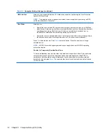
Страница 14: ...f Test POST messages Post Messages Disabled suppresses most POST messages such as memory count product name and other non error text messages If a POST error occurs the error is displayed regardless of the mode selected To manually switch to Post Messages Enabled during POST press any key except F1 through F12 Establish an Ownership Tag the text of which is displayed each time the system is turned...

Страница 15: ... F10 to enter Computer Setup 4 A choice of five headings appears in the Computer Setup Utilities menu File Storage Security Power and Advanced 5 Use the arrow left and right keys to select the appropriate heading Use the arrow up and down keys to select the option you want then press Enter To return to the Computer Setup Utilities menu press Esc 6 To apply and save changes select File Save Changes...

Страница 16: ...a Saves system configuration including CMOS to a formatted 1 44 MB diskette a USB flash media device or a diskette like device a storage device set to emulate a diskette drive Restore from Removable Media Restores system configuration from a diskette a USB flash media device or a diskette like device Default Setup Save Current Settings as Default Saves the current system configuration settings as ...

Страница 17: ...rs per track used by the BIOS to translate disk I O requests from the operating system or an application into terms the hard drive can accept Logical cylinders may not exceed 1024 The number of heads may not exceed 256 The number of sectors per track may not exceed 63 These fields are only visible and changeable when the drive translation mode is set to User Default Values Allows you to specify th...

Страница 18: ...Specify the order of attached hard drives The first hard drive in the order will have priority in the boot sequence and will be recognized as drive C if any devices are attached Press F5 to disable a device Press Enter to select a device Press the arrow keys to drag a selected device NOTE MS DOS drive lettering assignments may not apply after a non MS DOS operating system has started Shortcut to T...

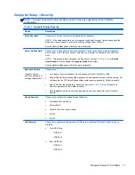
Страница 19: ...ons see below See the Desktop Management Guide for more information Password Options Appears only if a power on password or setup password is set Allows you to Lock legacy resources appears if a setup password is set Default is enable Enable Disable Setup Browse Mode appears if a setup password is set allows viewing but not changing the F10 Setup Options without entering setup password Default is ...

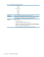
Страница 20: ...etwork controller must be either a PCI Express expansion card or embedded on the system board Default is enable System IDs Allows you to update Asset tag 18 byte identifier Ownership tag 80 byte identifier displayed during POST Chassis serial number or Universal Unique Identifier UUID number The UUID can only be updated if the current chassis serial number is invalid These ID numbers are normally ...

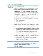
Страница 21: ...TE To configure the Embedded Security Device a Setup password must be set Reset to Factory Settings some models Do not reset Reset Resetting to factory defaults will erase all security keys Changing this setting requires turning the computer off and then back on Default is Do not reset CAUTION The embedded security device is a critical component of many security schemes Erasing the security keys w...

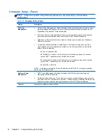
Страница 22: ... sleep state the system is in Each sleep state has a unique blink pattern Default is disabled S0 On Solid green LED S3 Stand By 3 blinks at 1Hz 50 duty cycle followed by a pause of 2 seconds green LED repeated cycles of 3 blinks and a pause S4 Hibernation 4 blinks at 1Hz 50 duty cycle followed by a pause of 2 seconds green LED repeated cycles of 4 blinks and a pause S5 Soft Off LED is off NOTE If ...

Страница 23: ...ower strip you will not be able to use the suspend sleep feature or the Remote Management features POST Delay None 5 10 15 or 20 seconds Enabling this feature will add a user specified delay to the POST process This delay is sometimes needed for hard disks on some PCI cards that spin up very slowly so slowly that they are not ready to boot by the time POST is finished The POST delay also gives you...

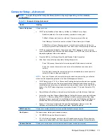
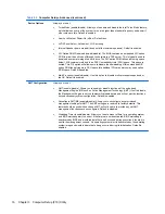
Страница 24: ...ble disable Use this option to disable multi processor support under the OS Default is enabled AMT Configuration Allows you to set AMT enable disable Allows you to enable or disable functions of the embedded Management Engine ME such as Active Management Technology AMT If set to disable the Management Engine is set to a temporarily disabled state and will not provide functions beyond necessary sys...

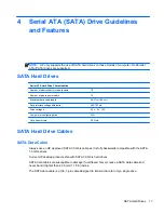
Страница 25: ...ial 400 700 mV Drive voltages 3 3 V 5 V 12 V Jumpers for configuring drive N A Data transfer rate 3 0 Gb s SATA Hard Drive Cables SATA Data Cable Always use an HP approved SATA 3 0 Gb s cable as it is fully backwards compatible with the SATA 1 5 Gb s drives Current HP desktop products ship with SATA 3 0 Gb s hard drives SATA data cables are susceptible to damage if overflexed Never crease a SATA d...

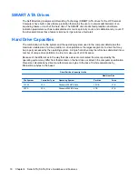
Страница 26: ...drive partition A drive partition is the largest segment of a drive that may be properly accessed by the operating system A single hard drive may therefore be subdivided into a number of unique drive partitions in order to make use of all of its space Because of the differences in the way that drive sizes are calculated the size reported by the operating system may differ from that marked on the h...

Страница 27: ...he procedures and precautions described in this chapter is essential for proper service CAUTION When the computer is plugged into an AC power source voltage is always applied to the system board You must disconnect the power cord from the power source before opening the computer to prevent system board or component damage 19 ...

Страница 28: ...moving DIPs from plastic tube 7 500 V 3 000 V 400 V 400 V 15 000 V 5 000 V 800 V 700 V 35 000 V 12 000 V 6 000 V 2 000 V Removing DIPs from vinyl tray Removing DIPs from Styrofoam Removing bubble pack from PCB Packing PCBs in foam lined box 2 000 V 3 500 V 7 000 V 5 000 V 4 000 V 5 000 V 20 000 V 11 000 V 11 500 V 14 500 V 26 500 V 21 000 V These are then multi packaged inside plastic tubes trays ...

Страница 29: ...atic plastic Carbon loaded plastic Metallized laminate 1 500 7 500 15 000 Grounding the Work Area To prevent static damage at the work area use the following precautions Cover the work surface with approved static dissipative material Provide a wrist strap connected to the work surface and properly grounded tools and equipment Use static dissipative mats foot straps or air ionizers to give added p...

Страница 30: ...arance on all vented sides of the computer and above the monitor to permit the required airflow Never restrict the airflow into the computer by blocking any vents or air intakes Do not place the keyboard with the keyboard feet down directly against the front of the desktop unit as this also restricts airflow Occasionally clean the air vents on all vented sides of the computer Lint dust and other f...

Страница 31: ...mpened with clear water For stubborn stains use isopropyl rubbing alcohol No rinsing is needed as the alcohol will evaporate quickly and not leave a residue After cleaning always wipe the unit with a clean lint free cloth Occasionally clean the air vents on the computer Lint and other foreign matter can block the vents and limit the airflow Cleaning the Keyboard Follow all safety precautions in Ge...

Страница 32: ...Before cleaning the mouse ensure that the power to the computer is turned off Clean the mouse ball by first removing the retaining plate and the ball from the housing Pull out any debris from the ball socket and wipe the ball with a clean dry cloth before reassembly To clean the mouse body follow the procedures in Cleaning the Computer Case on page 23 Service Considerations Listed below are some o...

Страница 33: ...gile Handle With Care Do not remove hard drives from the shipping package for storage Keep hard drives in their protective packaging until they are actually mounted in the CPU Avoid dropping drives from any height onto any surface If you are inserting or removing a hard drive turn off the computer Do not remove a hard drive while the computer is on or in standby mode Before handling a drive ensure...

Страница 34: ...posed of together with the general household waste In order to forward them to recycling or proper disposal please use the public collection system or return them to HP their authorized partners or their agents 26 Chapter 5 Routine Care and Disassembly Preparation ...

Страница 35: ...bezel HP 669989 001 Compaq 669990 001 2 Display panels 18 5 inch non ZBD 200 nits 671542 001 3 Rear cover does not include stand 669985 001 4 Foot assembly 669986 001 5 Side I O panel 669987 001 6 Stand 669988 001 Mylar for use on stand hinge not illustrated 669994 001 Computer major components 27 ...

Страница 36: ... number 1 Display cable LVDS 669996 001 2 Optical drive cable 669998 002 3 Inverter cable 669999 001 4 Hard drive cable 669997 001 5 Webcam cable 669995 001 Antenna not illustrated 669974 001 28 Chapter 6 Illustrated parts catalog ...

Страница 37: ...rd includes replacement thermal material 669973 001 2 Inverter board 669972 001 3 WLAN module 802 11b g n 634906 001 4 Webcam module 669982 001 Memory modules PC3 10600 1333 MHz not illustrated 4 GB 646801 001 2 GB 646800 001 1 GB 647448 001 Boards 29 ...

Страница 38: ... Rubber grommet for use in hard drive cage 669991 001 Power supply 90W external not illustrated 646779 001 Mouse USB optical not illustrated 596410 001 Mouse wireless not illustrated 625685 001 Keyboard not illustrated USB 537924 xx1 Wireless 665719 xx1 30 Chapter 6 Illustrated parts catalog ...

Страница 39: ...90371 D01 For use in Brazil 490371 202 For use in Denmark 490371 081 For use in Europe 490371 021 For use in Israel 490371 BB1 For use in Italy 490371 061 For use in South Africa 490371 AR1 For use in Switzerland 490371 111 For use in the United Kingdom 490371 031 For use in the United States 490371 001 Sequential part number listing Spare part number Description 485603 001 HP SuperMulti DVD Write...

Страница 40: ... for use in French Canada 537924 131 Keyboard USB for use in Portugal 537924 141 Keyboard USB for use in Turkey 537924 151 Keyboard USB for use in Greece 537924 161 Keyboard USB for use in Latin American Spanish 537924 181 Keyboard USB for use in Belgium 537924 201 Keyboard USB for use in Brazil 537924 211 Keyboard USB for use in Hungary 537924 221 Keyboard USB for use in the Czech Republic 537924...

Страница 41: ... Canada 665719 161 Keyboard wireless for use in Latin American Spanish 665719 201 Keyboard wireless for use in Brazil 669972 001 Inverter cable 669974 001 Antenna 669979 001 Display panel CMO 669980 001 Display panel BOE 669981 001 Fan blower 669986 001 Foot assembly 669987 001 Side I O panel 669988 001 Stand 669989 001 Front bezel HP 669990 001 Front bezel Compaq 669991 001 Rubber grommet for use...

Страница 42: ... DVD etc from the computer 2 Shut down the computer 3 After the system has completely shut down disconnect the power adapter from the back of the computer 4 Disconnect all other attached cables from the back of the computer 5 Place the computer face down on a soft flat surface HP recommends that you set down a blanket towel or other soft cloth to protect the screen surface from scratches or other ...

Страница 43: ... stand To remove the rear cover 1 Prepare the computer for disassembly see Preparing to Disassemble the Computer on page 34 2 Loosen the captive two Phillips screws 1 that secure the cover to the computer 3 Remove the non captive Phillips screw 2 that secures the cover to the computer 4 Lift the cover off the computer 3 Figure 7 1 Removing the rear cover To replace the rear cover reverse the remov...

Страница 44: ...e the stand 1 Prepare the computer for disassembly see Preparing to Disassemble the Computer on page 34 2 Remove the rear cover see Rear Cover on page 35 3 From the inside of the rear cover remove the four screws that secure the stand to the cover Figure 7 2 Removing the stand screws 36 Chapter 7 Removal and Replacement Procedures All in One AIO Chassis ...

Страница 45: ...4 Slide the stand bracket through the slot in the rear cover and then remove the stand from the rear cover Figure 7 3 Removing the stand To replace the stand reverse the removal procedures Stand 37 ...

Страница 46: ...he inside screw is smaller than the two outside screws Figure 7 4 Foot assembly location To remove the foot assembly 1 Prepare the computer for disassembly see Preparing to Disassemble the Computer on page 34 2 Remove the rear cover see Rear Cover on page 35 38 Chapter 7 Removal and Replacement Procedures All in One AIO Chassis ...

Страница 47: ...six screws that secure the foot assembly to the computer Figure 7 5 Removing the foot assembly 4 Lift the foot assembly from the computer To replace the foot assembly reverse the removal procedures Foot assembly 39 ...

Страница 48: ...verter board 1 Prepare the computer for disassembly see Preparing to Disassemble the Computer on page 34 2 Remove the rear cover see Rear Cover on page 35 3 Disconnect the three cables from the board 1 NOTE Be careful not to damage the cables when disconnecting them from the board Do not pull on the wires 4 Remove the two screws 2 that secure the board to the computer 40 Chapter 7 Removal and Repl...

Страница 49: ...5 Lift the inverter board from the computer 3 Figure 7 7 Removing the inverter board To install the inverter board or cable reverse the removal procedures Inverter Board 41 ...

Страница 50: ...d have separate cables and system board connectors Figure 7 8 Speaker location To remove the speakers 1 Prepare the computer for disassembly see Preparing to Disassemble the Computer on page 34 2 Remove the rear cover see Rear Cover on page 35 3 Disconnect the two speaker cables 1 from the system board 42 Chapter 7 Removal and Replacement Procedures All in One AIO Chassis ...

Страница 51: ...rom the computer 3 Figure 7 9 Removing the left speaker 5 Remove two screws 1 that secure the right speaker to the computer and then lift the speaker from the computer 2 Figure 7 10 Removing the right speaker Use the following image to determine correct routing for the speaker cables Speakers 43 ...

Страница 52: ...Figure 7 11 Speaker cable routing To install the speakers reverse the removal procedures 44 Chapter 7 Removal and Replacement Procedures All in One AIO Chassis ...

Страница 53: ...cated on the left side of the computer viewed from behind under the inverter board It is secured with one screw Figure 7 12 Optical drive location To remove the optical drive 1 Prepare the computer for disassembly see Preparing to Disassemble the Computer on page 34 2 Remove the rear cover see Rear Cover on page 35 3 Loosen the captive Phillips screw 1 that secures the drive to the computer Optica...

Страница 54: ...rive out of the bay and then slide the drive out of the computer 3 Figure 7 13 Removing the optical drive To install an optical drive reverse the removal procedures 46 Chapter 7 Removal and Replacement Procedures All in One AIO Chassis ...

Страница 55: ... 1 Prepare the computer for disassembly see Preparing to Disassemble the Computer on page 34 2 Remove the rear cover see Rear Cover on page 35 3 Remove the optical drive see Optical Drive on page 45 4 Remove two screws that secure the optical drive connector 1 to the computer 5 Disconnect the optical drive power and data cables 2 from the system board NOTE Be careful not to damage the cable when d...

Страница 56: ...onnector from the computer Figure 7 15 Removing the optical drive connector To install the optical drive connector reverse the removal procedures 48 Chapter 7 Removal and Replacement Procedures All in One AIO Chassis ...

Страница 57: ...from behind The drive is secured with one captive screw and is housed in a removable cage Figure 7 16 Hard drive location 1 Prepare the computer for disassembly see Preparing to Disassemble the Computer on page 34 2 Prepare the computer for disassembly see Preparing to Disassemble the Computer on page 34 3 Loosen the captive Phillips screw that secures the drive to the computer 1 Hard Drive 49 ...

Страница 58: ...f the computer 3 Figure 7 17 Removing the hard drive cage 5 Remove the four mounting Phillips screws 1 that secure the drive to the cage Do not remove the blue rubber grommets behind each screw They must stay attached to the cage when installing a new hard drive 50 Chapter 7 Removal and Replacement Procedures All in One AIO Chassis ...

Страница 59: ...ing the hard drive from the cage To replace the hard drive reverse the removal procedures NOTE Make sure the grommets are not broken or missing before installing the hard drive Replacement grommets are available using spare part number 669991 001 Hard Drive 51 ...

Страница 60: ...ng to Disassemble the Computer on page 34 2 Remove the rear cover see Rear Cover on page 35 3 Remove the hard drive see Hard Drive on page 49 4 Disconnect the hard drive power and data cables 1 from the system board NOTE Be careful not to damage the cable when disconnecting it from the board Do not pull on the wires 5 Remove two screws that secure the hard drive connector 2 to the computer 6 Remov...

Страница 61: ...7 Remove the connector from the computer 3 Figure 7 20 Removing the hard drive connector To install the hard drive connector reverse the removal procedures Hard Drive Cables and Connector 53 ...

Страница 62: ...overed by a bracket and is secured with two screws Figure 7 21 Fan location To remove the fan 1 Prepare the computer for disassembly see Preparing to Disassemble the Computer on page 34 2 Remove the rear cover see Rear Cover on page 35 54 Chapter 7 Removal and Replacement Procedures All in One AIO Chassis ...

Страница 63: ... bracket 4 Disconnect the fan cable 1 from the system board connector 5 Remove the three screws 2 that secure the fan to the computer 6 Lift the fan slightly and then slide the fan assembly away from the system board and remove it from the computer 3 Figure 7 23 Removing the fan assembly To install the fan reverse the removal procedures Fan 55 ...

Страница 64: ...puter viewed from behind Press the tabs to remove it Figure 7 24 Side I O cover location To remove the side I O cover 1 Prepare the computer for disassembly see Preparing to Disassemble the Computer on page 34 2 Remove the rear cover see Rear Cover on page 35 56 Chapter 7 Removal and Replacement Procedures All in One AIO Chassis ...

Страница 65: ... away from the computer 2 NOTE To help disengage the panel you can press the tab on the left side of the panel when pulling it away from the computer to remove it Figure 7 25 Removing the side I O cover To replace the side I O cover reverse the removal procedures Side I O Cover 57 ...

Страница 66: ...Webcam module location To remove the webcam module 1 Prepare the computer for disassembly see Preparing to Disassemble the Computer on page 34 2 Remove the rear cover see Rear Cover on page 35 3 Pull back on the tabs 1 that secure the module to the computer and lift the module from the computer as far as the cable allows 2 58 Chapter 7 Removal and Replacement Procedures All in One AIO Chassis ...

Страница 67: ... to remove the webcam cable disconnect the cable from the webcam module 1 remove the cable from the metal clips built into the computer 2 disconnect the cable from the system board 3 and then remove the cable from the computer Figure 7 28 Removing the webcam cable To install a webcam module reverse the removal procedures Webcam Module 59 ...

Страница 68: ... board cover 1 Prepare the computer for disassembly see Preparing to Disassemble the Computer on page 34 2 Remove the rear cover see Rear Cover on page 35 3 Remove the four Torx screws 1 that secure the system board cover to the computer 4 Slide the cover toward the side of the computer 2 60 Chapter 7 Removal and Replacement Procedures All in One AIO Chassis ...

Страница 69: ...r side of the cover up to a 45 degree angle and then lift the cover off the computer 3 Figure 7 30 Removing the system board cover To install the system board cover reverse the removal procedures System Board Cover 61 ...

Страница 70: ...liant 1 5 volt DDR3 SDRAM SODIMMs The DDR3 SDRAM SODIMMs must also support CAS latency 9 DDR3 1333 MHz 9 9 9 timing contain the mandatory Joint Electronic Device Engineering Council JEDEC specification In addition the computer supports 512 Mbit 1 Gbit and 2 Gbit non ECC memory technologies single sided and double sided SODIMMS SODIMMs constructed with x8 and x16 devices SODIMMs constructed with x4...

Страница 71: ...n each side of the SODIMM 1 allow the module to lift up to about a 45 degree angle and then pull the SODIMM out of the socket 2 Figure 7 31 Removing a memory module The computer automatically recognizes the additional memory when you turn on the computer Memory 63 ...

Страница 72: ...odule 1 Prepare the computer for disassembly see Preparing to Disassemble the Computer on page 34 2 Remove the rear cover see Rear Cover on page 35 3 Remove the system board cover see System Board Cover on page 60 4 Disconnect the antenna cable from the module 1 5 Remove the Phillips screw 2 that secures the module to the computer 64 Chapter 7 Removal and Replacement Procedures All in One AIO Chas...

Страница 73: ... 3 and then pull it away to remove it from the socket 4 Figure 7 33 Removing the WLAN module To install the WLAN module reverse the removal procedures NOTE WLAN modules are designed with a notch to prevent incorrect insertion WLAN Module 65 ...

Страница 74: ...ee Preparing to Disassemble the Computer on page 34 2 Remove the rear cover see Rear Cover on page 35 3 Remove the system board cover see System Board Cover on page 60 4 Disconnect the cable from the system board 1 5 Disconnect the cable from the display panel by pressing in the latches on the side of the cable connector 2 and pulling it from the connector 3 66 Chapter 7 Removal and Replacement Pr...

Страница 75: ... the cable from the metal clips 4 built into the computer Figure 7 35 Removing the display cable 7 Remove the cable from the computer To install the display cable reverse the removal procedures Display Cable 67 ...

Страница 76: ...system board cover see System Board Cover on page 60 4 Remove the memory module see Memory on page 62 5 Remove the WLAN module see WLAN Module on page 64 6 Disconnect all cables from the system board noting their location for reinstallation 7 Remove the nine screws circled in image that secure the system board to the computer Figure 7 36 Removing the system board 8 Lift the system board straight u...

Страница 77: ...l while removing the minimal number of components 1 Prepare the computer for disassembly see Preparing to Disassemble the Computer on page 34 2 Remove the rear cover see Rear Cover on page 35 3 Remove the system board cover see System Board Cover on page 60 4 Remove the side I O cover see Side I O Cover on page 56 5 Remove the webcam see Webcam Module on page 58 6 Remove the speakers see Speakers ...

Страница 78: ... see Rear Cover on page 35 3 Remove the system board cover see System Board Cover on page 60 4 Disconnect the speaker cables from the system board see Speakers on page 42 5 Remove the front bezel see Front Bezel on page 69 6 Remove the two screws that secure the display panel to the bracket Figure 7 38 Removing the display panel screws 7 Remove the two screws that secure the display panel to the b...

Страница 79: ...ct the display cable from the display panel Figure 7 40 Disconnecting the display cable 11 Lift the bracket assembly off the display panel To install a display panel reverse the removal procedures Display Panel 71 ...

Страница 80: ...the hard drive self test in Computer Setup Check the Power LED on the front of the computer to see if it is flashing red The flashing lights are error codes that will help you diagnose the problem Refer to Appendix A POST Error Messages on page 111 for more information If the screen is blank plug the monitor into a different video port on the computer if one is available Or replace the monitor wit...

Страница 81: ...ata on the hard drive Be sure to back up all data files before running the restore process NOTE For sales information and warranty upgrades Care Packs call your local authorized service provider or dealer Helpful Hints If you encounter problems with the computer monitor or software see the following list of general suggestions before taking further action Check that the computer and monitor are pl...

Страница 82: ...rom the system before turning it on If you have installed an operating system other than the factory installed operating system check to be sure that it is supported on the system If the system has multiple video sources embedded PCI or PCI Express adapters installed embedded video on some models only and a single monitor the monitor must be plugged into the monitor connector on the source selecte...

Страница 83: ...eyboard or mouse Cause Solution Computer is in standby mode To resume from standby mode press the power button or press any key CAUTION When attempting to resume from standby mode do not hold down the power button for more than four seconds Otherwise the computer will shut down and you will lose any unsaved data System has locked up Restart computer Computer date and time display is incorrect Caus...

Страница 84: ...ve Low on memory Add more memory Hard drive fragmented Defragment hard drive Program previously accessed did not release reserved memory back to the system Restart the computer Virus resident on the hard drive Run virus protection program Too many applications running 1 Close unnecessary applications to free up memory 2 Add more memory Some applications run in the background and can be closed by r...

Страница 85: ...ot flashing Cause Solution System unable to power on Press and hold the power button for less than 4 seconds If the hard drive LED turns green then 1 Check that the voltage selector located on the rear of the power supply on some models is set to the appropriate voltage Proper voltage setting depends on your region 2 Remove the expansion cards one at a time until the 5V_aux light on the system boa...

Страница 86: ... is not spinning make sure the fan s cable is plugged onto the system board header 3 If fan is plugged in but is not spinning then replace the heat sink fan assembly 4 Contact an authorized reseller or service provider Power LED flashes Red four times once every second followed by a two second pause and the computer beeps four times Beeps stop after fifth iteration but LEDs continue flashing Cause...

Страница 87: ...ecking click Check Now Diskette is incorrectly inserted Remove diskette and reinsert Drive cable is not properly connected Reconnect drive cable Ensure that all four pins on the diskette power cable are connected to the drive Drive not found Cause Solution Cable is loose Reseat diskette drive data and power cable Removable drive is not seated properly Reseat the drive The device has been hidden in...

Страница 88: ...kette Write in Storage Storage Options A problem has occurred with a disk transaction Cause Solution The directory structure is bad or there is a problem with a file In Microsoft Windows XP right click Start click Explore and select a drive Select File Properties Tools Under Error checking click Check Now In Microsoft Windows Vista or Windows 7 right click Start click Explore and right click on a ...

Страница 89: ...te Cause Solution Diskette is not bootable Replace with a bootable diskette Diskette boot has been disabled in Computer Setup 1 Run Computer Setup and enable USB device in Storage Boot Order 2 Run Computer Setup and enable USB device in Storage Storage Options Removable Media Boot NOTE Both steps should be used as the Removable Media Boot function in Computer Setup overrides the Boot Order enable ...

Страница 90: ...nd right click on a drive Select Properties then select the Tools tab Under Error checking click Check Now Drive not found identified Cause Solution Cable could be loose Check cable connections The system may not have automatically recognized a newly installed device See reconfiguration directions in the Solving Hardware Installation Problems on page 96 section If the system still does not recogni...

Страница 91: ...d as first in a multi hard drive configuration If attempting to boot from a hard drive ensure it is attached to the system board dark blue SATA connector Bootable hard drive s controller is not listed first in the Boot Order Run the Computer Setup utility and select Storage Boot Order and ensure the bootable hard drive s controller is listed immediately under the Hard Drive entry Computer will not...

Страница 92: ...er supply to make sure it is properly connected to the rear of the enclosure frame The removable hard drive is not recognized by the computer Cause Solution The removable hard drive carrier is not fully seated in the enclosure frame or the hard drive is not fully seated in the carrier Push the carrier into the enclosure frame so that the connector on the rear of the frame is properly seated If thi...

Страница 93: ...emory Stick PRO card make sure that the lock tab located on the bottom of the Memory Stick PRO card is not in the locked position Can not write to the media card Cause Solution The media card is a read only memory ROM card Check the manufacturer s documentation included with your card to see if it writable Refer to the previous section for a list of compatible cards Media card is locked Locking th...

Страница 94: ...lution The operating system needs time to recognize the device if the reader was just installed into the computer and you are turning the PC on for the first time Wait a few seconds so that the operating system can recognize the reader and the available ports and then recognize whatever media is inserted in the reader After inserting a media card in the reader the computer attempts to boot from th...

Страница 95: ...n accept the same horizontal scan rate as the resolution chosen Computer is in standby mode Press the power button to resume from standby mode CAUTION When attempting to resume from standby mode do not hold down the power button for more than four seconds Otherwise the computer will shut down and you will lose any unsaved data Monitor cable is plugged into the wrong connector Systems may have a mo...

Страница 96: ...e graphics card 3 Replace the system board For systems with integrated graphics replace the system board Blank screen and the power LED flashes Red seven times once every second followed by a two second pause and the computer beeps seven times Beeps stop after fifth iteration but LEDs continue flashing Cause Solution System board failure ROM detected failure prior to video Replace the system board...

Страница 97: ...hts or fans may be too close to the monitor Monitor needs to be degaussed Degauss the monitor Refer to the documentation that came with the monitor for instructions Image is not centered Cause Solution Position may need adjustment Press the monitor s Menu button to access the OSD menu Select ImageControl Horizontal Position or Vertical Position to adjust the horizontal or vertical position of the ...

Страница 98: ...ors using an analog VGA input connection only Cause Solution Flat panel monitor s internal digital conversion circuits may be unable to correctly interpret the output synchronization of the graphics card 1 Select the monitor s Auto Adjustment option in the monitor s on screen display menu 2 Manually synchronize the Clock and Clock Phase on screen display functions To download a SoftPaq that will a...

Страница 99: ...ned down or muted Double click the Speaker icon on the taskbar then make sure that Mute is not selected and use the volume slider to adjust the volume Audio is hidden in Computer Setup Enable the audio in Computer Setup Security Device Security System Audio The external speakers are not turned on Turn on the external speakers The audio device may be connected to the wrong jack Ensure that the devi...

Страница 100: ...ication has selected the correct audio device The operating system controls may be set to use a different audio device as the default output device than what is expected Set the operating system to use the correct audio device Sound from headphones is not clear or muffled Cause Solution Headphones are plugged into the rear audio output connector The rear audio output connector is for powered audio...

Страница 101: ...ing table Table A 8 Solving Printer Problems Printer will not print Cause Solution Printer is not turned on and online Turn the printer on and make sure it is online The correct printer drivers for the application are not installed 1 Install the correct printer driver for the application 2 Try printing using the MS DOS command DIR C printer port where printer port is the address of the printer bei...

Страница 102: ... Windows Vista or Windows 7 Desktop click Start click the arrow on the lower right corner of the Start menu then select Shut Down 2 After the shutdown is complete reconnect the keyboard to the back of the computer and restart the computer Program in use has stopped responding to commands Shut down your computer using the mouse and then restart the computer Keyboard needs repairs See the Worldwide ...

Страница 103: ...puter Mouse may need cleaning Remove the roller ball cover on the mouse and clean the internal components Mouse may need repair See the Worldwide Limited Warranty for terms and conditions Computer is in standby mode Press the power button to resume from standby mode CAUTION When attempting to resume from standby mode do not hold down the power button for more than four seconds Otherwise the comput...

Страница 104: ...er switch of new external device is not turned on Turn off the computer turn on the external device then turn on the computer to integrate the device with the computer system When the system advised you of changes to the configuration you did not accept them Reboot the computer and follow the instructions for accepting the changes A plug and play board may not automatically configure when added if...

Страница 105: ...t LEDs continue flashing Cause Solution Graphics card is not seated properly or is bad or system board is bad For systems with a graphics card 1 Reseat the graphics card Power on the system 2 Replace the graphics card 3 Replace the system board For systems with integrated graphics replace the system board Power LED flashes Red ten times once every second followed by a two second pause and the comp...

Страница 106: ... the check box to Allow this device to bring the computer out of standby To enable Wake on LAN in Windows Vista 1 Select Start Control Panel 2 Under Network and Internet select View network status and tasks 3 In the Tasks list select Manage network connections 4 Double click Local Area Connection 5 Click the Properties button 6 Click the Configure button 7 Click the Power Management tab then selec...

Страница 107: ...er Setup and enable network controller 2 Enable the network controller in the operating system via Device Manager Network driver is not properly loaded Reinstall network drivers System cannot autosense the network Disable auto sensing capabilities and force the system into the correct operating mode Diagnostics reports a failure Cause Solution The cable is not securely connected Ensure that the ca...

Страница 108: ...licts with the embedded NIC Under the Computer Setup Advanced menu change the resource settings for the board Network controller stops working without apparent cause Cause Solution The files containing the network drivers are corrupted Reinstall the network drivers using the Recovery Disc Set created from the hard drive s Recovery Partition The cable is not securely connected Ensure that the cable...

Страница 109: ... other management functions Table A 13 Solving Memory Problems System will not boot or does not function properly after installing additional memory modules Cause Solution A memory module is not installed in the DIMM1 or XMM1 socket Ensure that a memory module is installed in the DIMM1 or XMM1 socket on the system board This socket must be populated with a memory module Memory module is not the co...

Страница 110: ...isolate the faulty module 3 Replace third party memory with HP memory 4 Replace the system board Solving Processor Problems If you encounter processor problems common causes and solutions are listed in the following table Table A 14 Solving Processor Problems Poor performance is experienced Cause Solution Processor is hot 1 Make sure the airflow to the computer is not blocked 2 Make sure the fans ...

Страница 111: ...abled in Computer Setup Run the Computer Setup utility and disable Network Server Mode in Security Password Options Non bootable CD in drive Try a bootable CD in the drive Boot order not correct Run the Computer Setup utility and change boot sequence in Storage Boot Order Drive not found identified Cause Solution Cable could be loose Check cable connections The system may not have automatically re...

Страница 112: ...gency eject hole and push firmly Slowly pull the tray out from the drive until the tray is fully extended then remove the disc CD ROM CD RW DVD ROM or DVD R RW drive cannot read a disc or takes too long to start Cause Solution Media has been inserted upside down Re insert the media with the label facing up The DVD ROM drive takes longer to start because it has to determine the type of media played...

Страница 113: ...ice is attached to a USB port that has been hidden in Computer Setup Run the Computer Setup utility and ensure that Device available is selected for Front USB Ports and Rear USB Ports under Security Device Security The device was not properly seated before power up Ensure the device is fully inserted into the USB port before applying power to the system System will not boot from USB flash drive Ca...

Страница 114: ...ot working 1 Replace the device 2 Restart the computer USB ports on the computer are disabled in Computer Setup Run the Computer Setup utility and ensure that Device available is selected for appropriate USB ports under Security USB Security Solving Internet Access Problems If you encounter Internet access problems consult your Internet Service Provider ISP or refer to the common causes and soluti...

Страница 115: ...er can store temporarily with the Web browser This is useful for having the browser remember some specific information that the Web server can later retrieve Windows 7 1 Select Start Control Panel 2 Click Network and Internet 3 Click Internet Options 4 In the Browsing history section on the General tab click the Delete button 5 Select the Cookies check box and click the Delete button Windows Vista...

Страница 116: ...le click System 3 Click the Hardware tab 4 In the Device Manager area click the Device Manager button 5 Double click Modems 6 Double click Agere Systems PCI SV92PP Soft Modem 7 On the General tab click Diagnostics 8 Click Query Modem A Success response indicates the modem is connected and working properly Windows Vista 1 Select Start Control Panel 2 Click on System and Maintenance 3 Click on Syste...

Страница 117: ... has appeared Cause Solution POST error has occurred Observe the beeps and LED lights on the front of the computer See Appendix A POST Error Messages on page 111 to determine possible causes See the Restore Kit or the Worldwide Limited Warranty for terms and conditions Computer will not continue after HP logo screen has appeared Cause Solution System files may be damaged Use recovery diskette to s...

Страница 118: ...ttp www hp com NOTE If you take the computer to an authorized reseller dealer or service provider for service remember to provide the setup and power on passwords if they are set Refer to the number listed in the warranty or in the Support Telephone Numbers guide for technical assistance 110 Appendix A Troubleshooting Without Diagnostics ...

Страница 119: ...ge To manually switch to the POST Messages Enabled mode during POST press any key except F10 F11 or F12 The default mode is POST Message Disabled The speed at which the computer loads the operating system and the extent to which it is tested are determined by the POST mode selection Quick Boot is a fast startup process that does not run all of the system level tests such as the memory test Full Bo...

Страница 120: ...added remove it to see if the problem remains 2 In Computer Setup set Advanced Device Options NIC PXE Option ROM Download to DISABLE to prevent PXE option ROM for the internal NIC from being downloaded during POST to free more memory for an expansion card s option ROM Internal PXE option ROM is used for booting from the NIC to a PXE server 162 System Options Not Set Configuration incorrect RTC rea...

Страница 121: ...ket identified in the error message is missing critical SPD information or is incompatible with the chipset 1 Verify proper memory module type 2 Try another memory socket 3 Replace DIMM with a module conforming to the SPD standard 214 DIMM Configuration Warning Populated DIMM Configuration is not optimized Rearrange the DIMMs so that each channel has the same amount of memory 219 ECC Memory Module...

Страница 122: ...nce last system startup No action required 917 Front Audio Not Connected Front audio harness has been detached or unseated from motherboard Reconnect or replace front audio harness 921 Device in PCI Express slot failed to initialize There is an incompatibility problem with this device and the system or PCI Express Link could not be retrained to an x1 Try rebooting the system If the error reoccurs ...

Страница 123: ... is proper intake and exhaust ventilation for the enclosure 2200 PMM Allocation Error during MEBx Download Memory error during POST execution of the Management Engine ME BIOS Extensions option ROM 1 Reboot the computer 2 Unplug the power cord re seat the memory modules and reboot the computer 3 If the memory configuration was recently changed unplug the computer restore the original memory configu...

Страница 124: ...irmware version 3 If the error still persists replace the system board 2217 ME Firmware Version request failure ME firmware is not properly responding to BIOS query for version information 1 Reboot the computer 2 If the error persists update to the latest BIOS version and ME firmware version 3 If the error still persists replace the system board 2218 ME Firmware Version should be updated ME firmwa...

Страница 125: ...ion and ME firmware version 3 If the error still persists replace the system board 2231 ME error during MEBx execution Error occurred during MEBx execution which fails into ME grouping 1 Reboot the computer 2 If the error persists update to the latest BIOS version and ME firmware version 3 If the error still persists replace the system board 2232 AMT error during MEBx execution Error occurred duri...

Страница 126: ...ard with computer turned off 2 Check connector for bent or missing pins 3 Ensure that none of the keys are depressed 4 Replace keyboard Parity Check 2 Parity RAM failure or a PCI PCIe device is asserting a SERR Run Computer Setup and Diagnostic utilities To disable a PCI PCIe device from asserting a SERR run the Computer Setup utility and select Advanced Bus Options SERR Generation Disable 118 App...

Страница 127: ...end to RAM mode some models only or normal Suspend mode None required Press any key or move the mouse to wake the computer Red Power LED flashes two times once every second followed by a two second pause Beeps stop after fifth iteration but LEDs continue until problem is solved 2 Thermal protection activated Air flow is restricted a fan may not be functioning or the heatsink is not properly attach...

Страница 128: ... solved 5 Pre video memory error CAUTION To avoid damage to the DIMMs or the system board you must unplug the computer power cord before attempting to reseat install or remove a DIMM module 1 Reseat DIMMs 2 Replace DIMMs one at a time to isolate the faulty module 3 Replace third party memory with HP memory 4 Replace the system board Red Power LED flashes six times once every second followed by a t...

Страница 129: ...1 The current processor does not support a feature previously enabled on this system 1 Install a TXT capable processor 2 Disable TXT in the Computer Setup F10 utility 3 Reinstall the original processor System does not power on and LEDs are not flashing None System unable to power on Press and hold the power button for less than 4 seconds If the hard drive LED turns green the power button is workin...

Страница 130: ...e connectors may not be used on the product being serviced Ethernet BNC Connector and Icon Pin Signal 1 2 Data Ground USB Connector and Icon Pin Signal 1 2 3 4 5 VDC Data Data Ground Microphone Connector and Icon 1 8 miniphone Pin Signal 1 Tip 2 Ring 3 Shield Audio_left Audio_Right Ground 122 Appendix C Connector Pin Assignments ...

Страница 131: ...Audio_left Power_Right Ground Line in Audio Connector and Icon 1 8 miniphone Pin Signal 1 Tip 2 Ring 3 Shield Audio_In_Left Audio_In_Right Ground Line out Audio Connector and Icon 1 8 miniphone Pin Signal 1 Tip 2 Ring 3 Shield Audio_Out_Left Audio_Out_Right Ground Headphone 123 ...

Страница 132: ...cy responsible for evaluation in the country where the power cord set will be installed 2 The power cord set must have a minimum current capacity of 10A 7A Japan only and a nominal voltage rating of 125 or 250 volts AC as required by each country s power system 3 The diameter of the wire must be a minimum of 0 75 mm2 or 18AWG and the length of the cord must be between 1 8 m 6 feet and 3 6 m 12 fee...

Страница 133: ... set fittings appliance coupler and wall plug must bear the certification mark of the agency responsible for evaluation in the country where it will be used 2 The flexible cord must be Type SVT or equivalent No 18 AWG 3 conductor The wall plug must be a two pole grounding type with a NEMA 5 15P 15A 125V or NEMA 6 15P 15A 250V configuration 3 Appliance coupler flexible cord and wall plug must bear ...

Страница 134: ...emperature Range Operating Nonoperating 41 to 95 F 22 to 149 F 5 to 35 C 30 to 66 C Relative Humidity noncondensing Operating 15 80 at 79 F 15 80 at 26 C Maximum Altitude unpressurized Operating Nonoperating 0 6 562 ft 0 15 000 ft 0 2000 m 4 572 m Power Supply Rated Voltage Range Rated Line Frequency 100 240 V 50 60 Hz 100 240 V 50 60 Hz Max Operating Power 90 W 90 W 126 Appendix E Specifications ...

Страница 135: ...e part number 33 E electrostatic discharge ESD 20 preventing damage 20 error codes 111 119 messages 112 ethernet BNC pin assignments 122 F fan removing 54 spare part number 30 33 features overview 1 flash drive problems 105 flashing LEDs 119 foot spare part number 27 33 foot assembly removing 38 front bezel removing 69 spare part number 27 front components 2 front panel problems 106 G general prob...

Страница 136: ... 93 processor 102 software 109 processor problems 102 R rear components 3 rear cover removing 35 spare part number 27 removal and replacement procedures 47 52 All in One chassis 34 display cable 66 display panel 70 fan 54 foot assembly 38 front bezel 69 hard drive 49 hard drive connector 52 inverter board 40 memory 62 optical drive 45 optical drive connector 47 preparing to disassemble the compute...

Страница 137: ...in assignments 122 V ventilation proper 22 W Wake on LAN feature 98 webcam cable spare part number 28 33 webcam module removing 58 spare part number 29 WLAN module removing 64 spare part number 29 33 Index 129 ...

Отзывы: