


3-20
Chapter 3
Gauging and Making Connections
Zeroing Connector Gauges
Zeroing Connector Gauges
For type-N gauges, the paired gauge master is labeled with an offset
value to compensate for its inaccuracy with its gauge. This label
appears on the bottom of all type-N gauge masters that have been
paired with gauges. When setting a type-N gauge with its master,
always set the gauge to the master offset value shown on the label, not
to zero, unless that is the offset value indicated.
The design of the 3.5 mm and 7 mm pin depth gauges are different than
the type-N gauge design. The 3.5 mm and 7 mm gauges do not require
any offsetting to compensate for inaccuracies in the gauge masters. For
the locations of the gauge masters for the 3.5 mm, 7 mm, and type-N
gauges, see
NOTE
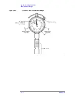
Hold a connector gauge by the gauge barrel, below the dial indicator.
This gives the best stability, and improves measurement accuracy.
Cradling the gauge in your hand or holding it by the dial applies stress
to the gauge plunger mechanism through the dial indicator housing.
Zeroing the Gauge
1. Select the proper gauge for your connector. Always use gauges which
are intended for pin depth measurements.
2. Inspect and clean the gauge:
a. Inspect the connector gauge and gauge master carefully, exactly
as you inspected the connector itself.
b. Clean or replace the gauge and gauge master if necessary. Dirt on
either the gauge or the gauge master makes gauge measurements
inaccurate, and can damage a connector.
NOTE
Check gauges often to make sure that the zero setting has not changed.
Generally, when the pointer on a recently zeroed gauge does not line up
with the zero mark exactly, the gauge or gauge master needs cleaning.
Clean both of these carefully and check the zero setting again.
Содержание HP 85060B
Страница 5: ...1 1 1 General Information ...
Страница 17: ...Chapter 1 1 13 General Information Safety and Regulatory Information ...
Страница 18: ...2 1 2 Specifications and Characteristics ...
Страница 36: ...3 1 3 Gauging and Making Connections ...
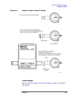
Страница 50: ...Chapter 3 3 15 Gauging and Making Connections Using Connector Gauges Figure 3 2 Typical 3 5 mm Connector Gauge ...
Страница 51: ...3 16 Chapter3 Gauging and Making Connections Using Connector Gauges Figure 3 3 Typical 7 mm Connector Gauge ...
Страница 52: ...Chapter 3 3 17 Gauging and Making Connections Using Connector Gauges Figure 3 4 Typical Type N Connector Gauge ...
Страница 61: ...3 26 Chapter3 Gauging and Making Connections Gauging Techniques Figure 3 8 Using a 3 5 mm Connector Gauge ...
Страница 65: ...3 30 Chapter3 Gauging and Making Connections Making Type F Connections Figure 3 9 Type F Female Connectors ...
Страница 67: ...4 1 4 Replaceable Parts ...