


Chapter 2
2-5
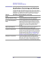
Specifications and Characteristics
Mechanical Characteristics
Mechanical Characteristics
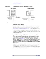
Center Conductor Pin Depth
Mechanical characteristics, such as center conductor protrusion and pin
depth, are not performance specifications. They are however, important
supplemental characteristics related to the electrical performance of
devices.
Hewlett-Packard verifies the mechanical characteristics of the devices
in this kit with special gauging processes and electrical testing. These
processes ensure that the device connectors do not exhibit any excess
center conductor protrusion and have the proper pin depth when the kit
leaves the factory.
Pin Depth
Pin depth is the distance the center conductor mating plane differs
from being flush with the outer connector mating plane (see
). The pin depth of a connector can be in one of two states:
either protruding or recessed.
NOTE
No protrusion of the center conductor shoulder is allowable on any
7 mm connector when the slotted collet is removed. The slotted collet
must be removed before measuring the pin depth.
Protrusion occurs when the center conductor extends beyond the
outer conductor mating plane. It reads as a positive value on the
connector gauge.
Recession occurs when the center conductor is set back from the outer
conductor mating plane. It reads as a negative value on the gauge.
NOTE
The center conductor protrusion or recession is referenced to the outer
conductor mating plane.
Содержание HP 85060B
Страница 5: ...1 1 1 General Information ...
Страница 17: ...Chapter 1 1 13 General Information Safety and Regulatory Information ...
Страница 18: ...2 1 2 Specifications and Characteristics ...
Страница 36: ...3 1 3 Gauging and Making Connections ...
Страница 50: ...Chapter 3 3 15 Gauging and Making Connections Using Connector Gauges Figure 3 2 Typical 3 5 mm Connector Gauge ...
Страница 51: ...3 16 Chapter3 Gauging and Making Connections Using Connector Gauges Figure 3 3 Typical 7 mm Connector Gauge ...
Страница 52: ...Chapter 3 3 17 Gauging and Making Connections Using Connector Gauges Figure 3 4 Typical Type N Connector Gauge ...
Страница 61: ...3 26 Chapter3 Gauging and Making Connections Gauging Techniques Figure 3 8 Using a 3 5 mm Connector Gauge ...
Страница 65: ...3 30 Chapter3 Gauging and Making Connections Making Type F Connections Figure 3 9 Type F Female Connectors ...
Страница 67: ...4 1 4 Replaceable Parts ...