


2-8
Chapter 2
Specifications and Characteristics
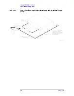
Connector Pin Depth Information
Connector Pin Depth Information
1
1. Hewlett-Packard does not supply pin depth gauges for type-F or 7-16 connectors. The type-F mod-
ule adapter pin depth is set at –25.4 to –50.8 micrometers. The 7-16 module adapter pin depth is
set at 0 to –38.1 micrometers recessed from the nominal 1.77 mm offset between inner conductor
and outer conductor mating planes.
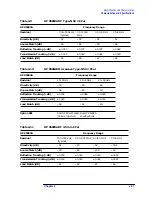
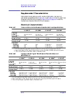
Table 2-3
3.5 mm Connector Pin Depth Limits
Device
Typical Pin Depth in
micrometers (10
–4
inches)
Measurement Uncertainty
1
in micrometers (10
–4
inches)
Observed Pin Depth Limits
in micrometers (10
–4
inches)
3.5 mm ECal Module
–25.4 to –50.8 (–10.0 to –20.0)
+1.3 to –1.3 (+0.5 to –0.5)
–24.1 to –52.1 (–9.5 to –20.5)
3.5 mm Adapter
–2.5 to –13.0 (–1.0 to –5.0)
+1.3 to –1.3 (+0.5 to –0.5)
–1.2 to –14.3 (–0.5 to –5.5)
1. Approxi2 sigma to –2 sigma of gauge uncertainty based on studies performed at the factory using analog gauges
according to recommended procedures.
Table 2-4
7 mm Connector Pin Depth Limits
Device
Typical Pin Depth in
micrometers (10
–4
inches)
Measurement Uncertainty
1
in micrometers (10
–4
inches)
Observed Pin Depth Limits
in micrometers (10
–4
inches)
7 mm ECal Module
–25.4 to –50.8 (–10.0 to –20.0)
+1.3 to –1.3 (+0.5 to –0.5)
–24.1 to –52.1 (–9.5 to –20.5)
1. Approxi2 sigma to –2 sigma of gauge uncertainty based on studies performed at the factory using analog gauges
according to recommended procedures.
Table 2-5
Type-N 50
Ω
Connector Pin Depth Limits
Device
Typical Pin Depth
1
in
micrometers (10
–4
inches)
Measurement Uncertainty
2
in micrometers (10
–4
inches)
Observed Pin Depth Limits
in micrometers (10
–4
inches)
Type-N 50
Ω
ECal Module –25.4 to –50.8 (–10.0 to –20.0) +3.8 to –3.8 (+1.5 to –1.5)
–21.6 to –54.6 (–8.5 to –21.5)
Type-N 50
Ω
Adapter
0 to –12.7 (0 to –5.0)
+3.8 to –3.8 (+1.5 to –1.5)
+3.8 to –16.5 (+1.5 to –6.5)
1. Measured from a 5.258 mm (0.207 inches) nominal offset.
2. Approxi2 sigma to –2 sigma of gauge uncertainty based on studies performed at the factory using analog gauges
according to recommended procedures.
Содержание HP 85060B
Страница 5: ...1 1 1 General Information ...
Страница 17: ...Chapter 1 1 13 General Information Safety and Regulatory Information ...
Страница 18: ...2 1 2 Specifications and Characteristics ...
Страница 36: ...3 1 3 Gauging and Making Connections ...
Страница 50: ...Chapter 3 3 15 Gauging and Making Connections Using Connector Gauges Figure 3 2 Typical 3 5 mm Connector Gauge ...
Страница 51: ...3 16 Chapter3 Gauging and Making Connections Using Connector Gauges Figure 3 3 Typical 7 mm Connector Gauge ...
Страница 52: ...Chapter 3 3 17 Gauging and Making Connections Using Connector Gauges Figure 3 4 Typical Type N Connector Gauge ...
Страница 61: ...3 26 Chapter3 Gauging and Making Connections Gauging Techniques Figure 3 8 Using a 3 5 mm Connector Gauge ...
Страница 65: ...3 30 Chapter3 Gauging and Making Connections Making Type F Connections Figure 3 9 Type F Female Connectors ...
Страница 67: ...4 1 4 Replaceable Parts ...