background image

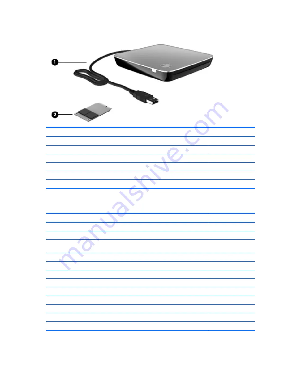
Mass storage devices

Item

Component

Spare part number

(1)

Optical drive:


Blu-ray ROM DVD±R/RW Super Multi Double-Layer Drive

659941-001


DVD±RW and CD-RW Super Multi Double-Layer Combo Drive

659940-001

(2)

Hard drive


 128-GB 

solid-state 

drive

672616-001

 Screws 

(not 

illustrated)

Miscellaneous parts

Component

Spare part number

HP AC adapter (non-smart):

65-W PFC RC V EM 3-wire HP AC adapter (non-smart) for use only in India

613149-001

65-W PFC RC V 3-wire HP AC adapter (non-smart) for use in all countries and regions except
India

613149-001

Power cord

 (3-pin, black, 1.83-m):

For use in Australia

490371-011

For use in Italy

490371-061

For use in North America

490371-001

For use in South Korea

490371-AD1

For use in Europe

490371-021

For use in Switzerland

490371–111

For use in the United Kingdom and Singapore

490371–031

Screw Kit

672359-001

16

Chapter 3   Illustrated parts catalog

Содержание Folio 13

Страница 1: ...HP Folio 13 2000 Maintenance and Service Guide ...

Страница 2: ...proprietor The information contained herein is subject to change without notice The only warranties for HP products and services are set forth in the express warranty statements accompanying such products and services Nothing herein should be construed as constituting an additional warranty HP shall not be liable for technical or editorial errors or omissions contained herein First Edition January...

Страница 3: ...w another hard surface such as an adjoining optional printer or a soft surface such as pillows or rugs or clothing to block airflow Also do not allow the AC adapter to contact the skin or a soft surface such as pillows or rugs or clothing during operation The device and the AC adapter comply with the user accessible surface temperature limits defined by the International Standard for Safety of Inf...

Страница 4: ...iv Safety warning notice ...

Страница 5: ...ss storage devices 16 Miscellaneous parts 16 Sequential part number listing 17 4 Removal and replacement procedures 19 Preliminary replacement requirements 19 Tools required 19 Service considerations 19 Plastic parts 19 Cables and connectors 19 Drive handling 20 Grounding guidelines 20 Electrostatic discharge damage 20 Packaging and transporting guidelines 22 Component replacement procedures 23 Se...

Страница 6: ... Navigating and selecting in Setup Utility 49 Displaying system information 49 Restoring factory settings in Setup Utility 50 Exiting Setup Utility 50 Updating the BIOS 50 Determining the BIOS version 51 Downloading a BIOS update 51 BIOS Setup Menu 52 Main menu 52 Security menu 52 Diagnostics menu 52 Using System Diagnostics 52 6 Specifications 54 Computer specifications 54 13 3 inch display speci...

Страница 7: ...ing Windows Backup and Restore 60 Using Windows system restore points 61 When to create restore points 61 Create a system restore point 61 Restore to a previous date and time 61 8 Power cord set requirements 62 Requirements for all countries 62 Requirements for specific countries and regions 62 9 Recycling 64 Index 65 vii ...

Страница 8: ...viii ...

Страница 9: ...ngle channel support DDR3 1600 downgrade to 1333 Supports up to 4096 GB of system RAM Supports 4096 MB total system memory 4096 1 configuration Hard drives mSATA SSD 128 GB 128 GB SSD Optical drive External USB optical drive computer USB ports support 2A current SATA 12 7 mm tray load Supports the following external optical drives Blu ray ROM DVD R RW Super Multi Double Layer Drive DVD RW and CD R...

Страница 10: ... version 1 3b supporting 1080p 1920 1080 60Hz RJ 45 Ethernet includes link and activity lights USB 3 0 1 port USB 2 0 1 port Keyboard pointing devices 97 Duracoat island style keyboard no spill resistance in black finish TouchPad with multi touch gestures Taps enabled as default Power requirements Supports the following HP AC adapters 65 W PFC RC V EM 3 wire HP AC adapter Supports the following ba...

Страница 11: ...2 External component identification 3 ...

Страница 12: ...r initiates Sleep if the display is closed while the power is on NOTE The display switch is not visible from the outside of the computer The antennas are not visible from the outside of the computer For optimal transmission keep the areas immediately around the antennas free from obstructions To see wireless regulatory notices refer to the section of the Regulatory Safety and Environmental Notices...

Страница 13: ...on NOTE For select models the Intel Rapid Start Technology feature is enabled at the factory Rapid Start Technology allows your computer to resume quickly from inactivity For more information refer to the HP Notebook User Guide If the computer has stopped responding and Windows shutdown procedures are ineffective press and hold the power button for at least 5 seconds to turn off the computer To le...

Страница 14: ...2 fn key Displays system information when pressed in combination with the esc key 3 Windows logo key Displays the Windows Start menu 4 Action keys Execute frequently used system functions 5 Windows applications key Displays a shortcut menu for items beneath the pointer 6 Chapter 2 External component identification ...

Страница 15: ... off or in Hibernation 2 Webcam light On The webcam is in use 3 Mute light Amber Computer sound is off Off Computer sound is on 4 Wireless light White An integrated wireless device such as a wireless local area network WLAN device and or a Bluetooth device is on Amber All wireless devices are off 5 Caps lock light On Caps lock is on Lights 7 ...

Страница 16: ...ouchPad button Functions like the left button on an external mouse 5 Right TouchPad button Functions like the right button on an external mouse Rear Component Description Vent Enables airflow to cool internal components NOTE The computer fan starts up automatically to cool internal components and prevent overheating It is normal for the internal fan to cycle on and off during routine operation 8 C...

Страница 17: ...gital or audio component 5 USB 3 0 port Connects optional USB 3 0 devices and provide enhanced USB power performance NOTE The USB 3 0 port is also compatible with USB 1 0 and USB 2 0 devices 6 Digital Media Slot Supports the following digital card formats Secure Digital SD Memory Card Secure Digital Extended Capacity SDxC Memory Card Secure Digital High Capacity SDHC Memory Card Ultra High Speed M...

Страница 18: ...phone WARNING To reduce the risk of personal injury adjust the volume before putting on headphones earbuds or a headset For additional safety information refer to the Regulatory Safety and Environmental Notices NOTE When a device is connected to the jack the computer speakers are disabled NOTE The microphone function is operational only when used with a headphone microphone unit that has a 4 condu...

Страница 19: ... Vent Enables airflow to cool internal components NOTE The computer fan starts up automatically to cool internal components and prevent overheating It is normal for the internal fan to cycle on and off during routine operation Bottom 11 ...

Страница 20: ...umber s n This is an alphanumeric identifier that is unique to each product 3 Part number Product number p n This number provides specific information about the product s hardware components The part number helps a service technician to determine what components and parts are needed 4 Warranty period This number describes the duration of the warranty period for the computer 5 Model description Thi...

Страница 21: ...Computer major components Item Component Spare part number 1 Display assembly 672350 001 2 Keyboard includes keyboard cable In black finish Computer major components 13 ...

Страница 22: ...r button board and cable and TouchPad and TouchPad cable 672357 001 5 TouchPad button board includes cable NOTE The top cover spare part kit includes the power button board and cable and the TouchPad and cable 672357 001 6 Power connector cable includes bracket 672361 001 7 Memory module 1 PC3 10600 1333 MHz 4 GB 641369 005 8 Hard drive does not include the hard drive bracket connector cable isola...

Страница 23: ...Item Component Spare part number 6 cell 55 Whr 2 55 Ah Li ion battery 671602 001 17 Base enclosure 672356 001 Computer major components 15 ...

Страница 24: ...non smart 65 W PFC RC V EM 3 wire HP AC adapter non smart for use only in India 613149 001 65 W PFC RC V 3 wire HP AC adapter non smart for use in all countries and regions except India 613149 001 Power cord 3 pin black 1 83 m For use in Australia 490371 011 For use in Italy 490371 061 For use in North America 490371 001 For use in South Korea 490371 AD1 For use in Europe 490371 021 For use in Swi...

Страница 25: ...cable and transceivers 672353 001 Speaker Kit includes left and right speakers and cable 672354 001 Fan Heat sink 672355 001 Fan Heat sink includes replacement thermal material 672356 001 Base enclosure 672357 001 Top cover in black finish includes power button board and cable and TouchPad and TouchPad cable 672358 001 USB Audio board 672359 001 Screw Kit 672361 001 Power connector cable includes ...

Страница 26: ...inish for use in The Netherlands includes keyboard cable 673656 BG1 Keyboard in black finish for use in Switzerland includes keyboard cable 673656 DH1 Keyboard in black finish for use in Denmark Finland Norway includes keyboard cable 682564 001 System board for use only with computer models equipped with an Intel 1 6 GHz processor includes processor and replacement thermal material 18 Chapter 3 Il...

Страница 27: ...reassembly can damage plastic parts Use care when handling the plastic parts Apply pressure only at the points designated in the maintenance instructions Cables and connectors CAUTION When servicing the computer be sure that cables are placed in their proper locations during the reassembly process Improper cable placement can damage the computer Cables must be handled with extreme care to avoid da...

Страница 28: ...charge damage Electronic components are sensitive to electrostatic discharge ESD Circuitry design and structure determine the degree of sensitivity Networks built into many integrated circuits provide some protection but in many cases ESD contains enough power to alter device parameters or melt silicon junctions A discharge of static electricity from a finger or other conductor can destroy static ...

Страница 29: ... 000 V Motions of bench worker 6 000 V 800 V 400 V Removing DIPS from plastic tube 2 000 V 700 V 400 V Removing DIPS from vinyl tray 11 500 V 4 000 V 2 000 V Removing DIPS from Styrofoam 14 500 V 5 000 V 3 500 V Removing bubble pack from PCB 26 500 V 20 000 V 7 000 V Packing PCBs in foam lined box 21 000 V 11 000 V 5 000 V Preliminary replacement requirements 21 ...

Страница 30: ...nd that proper materials are selected to avoid static charging When grounding is not possible use an ionizer to dissipate electric charges Workstation guidelines Follow these grounding workstation guidelines Cover the workstation with approved static shielding material Use a wrist strap connected to a properly grounded work surface and use properly grounded tools and equipment Use conductive field...

Страница 31: ...s and sleeve protectors Conductive bins and other assembly or soldering aids Nonconductive foam Conductive tabletop workstations with ground cords of one megohm resistance Static dissipative tables or floor mats with hard ties to the ground Field service kits Static awareness labels Material handling packages Nonconductive plastic bags tubes or boxes Metal tote boxes Electrostatic voltage levels a...

Страница 32: ...ponents and parts are needed 4 Warranty period This number describes the duration of the warranty period for the computer 5 Model description This is the alphanumeric identifier used to locate documents drivers and support for the computer Computer feet The computer feet are adhesive backed rubber pads There are 4 rubber feet that attach to the base enclosure in the locations illustrated below All...

Страница 33: ...omputer is off or in Hibernation turn the computer on and then shut it down through the operating system 2 Disconnect all external devices connected to the computer 3 Disconnect the power from the computer by first unplugging the power cord from the AC outlet and then unplugging the AC adapter from the computer Remove the base enclosure screws Component replacement procedures 25 ...

Страница 34: ...The keyboard spare part kit includes a keyboard cable For use in country or region Spare part number For use in country or region Spare part number Keyboard in black finish For use in the United States 673656 001 For use in Spain 673656 071 For use in Canada 673656 121 For use in the United Kingdom and Singapore 673656 031 For use in Germany 673656 041 For use in Italy 673656 061 For use in South ...

Страница 35: ...rd from the AC outlet and then unplugging the AC adapter from the computer 4 Remove the base enclosure screws see Base enclosure on page 25 Remove the keyboard 1 Turn the computer right side up with the front facing you 2 Partially open the computer 3 At the right side of the computer insert a screwdriver or similar thin tool into the top cover release area pressing upwards until the top cover sta...

Страница 36: ...ct all external devices connected to the computer 3 Disconnect the power from the computer by first unplugging the power cord from the AC outlet and then unplugging the AC adapter from the computer 4 Remove the base enclosure screws see Base enclosure on page 25 5 Remove the keyboard see Keyboard on page 26 When replacing the top cover be sure that the TouchPad button board and cable see TouchPad ...

Страница 37: ... 4 Lift the rear edge of the top cover until the left and right sides disengage from the base enclosure and remove the top cover Reverse this procedure to install the top cover Power button board Description Spare part number Power button board 672357 001 Component replacement procedures 29 ...

Страница 38: ...gging the AC adapter from the computer 4 Remove the base enclosure screws see Base enclosure on page 25 5 Remove the keyboard see Keyboard on page 26 6 Remove the top cover see Top cover on page 28 7 Disconnect the battery cable see Battery on page 32 Remove the Power button board and cable 1 Turn the top cover upside down with the back edge toward you 2 Remove the 2 Phillips PM 2 0x3x0 screws sec...

Страница 39: ...ging the power cord from the AC outlet and then unplugging the AC adapter from the computer 4 Remove the base enclosure screws see Base enclosure on page 25 5 Remove the keyboard see Keyboard on page 26 6 Remove the top cover see Top cover on page 28 Remove the TouchPad button board and cable 1 Turn the top cover upside down with the back edge toward you 2 Remove the 5 Phillips PM 2 0 3 8 screws 1...

Страница 40: ...er 3 Disconnect the power from the computer by first unplugging the power cord from the AC outlet and then unplugging the AC adapter from the computer 4 Remove the base enclosure screws see Base enclosure on page 25 5 Remove the keyboard see Keyboard on page 26 6 Remove the top cover see Top cover on page 28 Remove the battery 1 Turn the computer right side up with the front toward you 2 Disconnec...

Страница 41: ...battery slightly and then slide it forward 2 Remove the battery from the computer 3 CAUTION Make sure that you balance the battery carefully so that it is not damaged Reverse this procedure to install the battery Component replacement procedures 33 ...

Страница 42: ...base enclosure screws see Base enclosure on page 25 5 Remove the keyboard see Keyboard on page 26 6 Remove the top cover see Top cover on page 28 7 Disconnect the battery cable see Battery on page 32 Remove the display panel 1 Turn the computer right side up with the front toward you 2 Open the computer 3 Disconnect the display panel cable from the system board 1 4 Disconnect the USB Audio board c...

Страница 43: ...7 Remove the 5 screws 1 securing the display panel to the computer There are 3 screws on the left hinge and 2 screws on the right hinge NOTE Support the display panel as you are removing the screws 8 Lift and remove the display panel 2 Reverse this procedure to install the display panel Component replacement procedures 35 ...

Страница 44: ...the operating system 2 Disconnect all external devices connected to the computer 3 Disconnect the power from the computer by first unplugging the power cord from the AC outlet and then unplugging the AC adapter from the computer 4 Remove the base enclosure screws see Base enclosure on page 25 5 Remove the keyboard see Keyboard on page 26 6 Remove the top cover see Top cover on page 28 7 Disconnect...

Страница 45: ...ter is off or in Hibernation turn the computer on and then shut it down through the operating system 2 Disconnect all external devices connected to the computer 3 Disconnect the power from the computer by first unplugging the power cord from the AC outlet and then unplugging the AC adapter from the computer 4 Remove the base enclosure screws see Base enclosure on page 25 5 Remove the keyboard see ...

Страница 46: ...3 Remove the USB Audio board 3 38 Chapter 4 Removal and replacement procedures ...

Страница 47: ...om the computer 4 Remove the base enclosure screws see Base enclosure on page 25 5 Remove the keyboard see Keyboard on page 26 6 Remove the top cover see Top cover on page 28 7 Disconnect the battery cable see Battery on page 32 Remove the RTC battery 1 Disconnect the RTC battery cable from the system board 1 2 Remove the RTC battery 2 Use a thin non conductive tool to remove the RTC battery from ...

Страница 48: ...ugging the power cord from the AC outlet and then unplugging the AC adapter from the computer 4 Remove the base enclosure screws see Base enclosure on page 25 5 Remove the keyboard see Keyboard on page 26 6 Remove the top cover see Top cover on page 28 7 Disconnect the battery cable see Battery on page 32 Remove the hard drive 1 Remove the 2 Phillips PM 2 0 2 5 screws 1 that secure the hard drive ...

Страница 49: ...ugging the AC adapter from the computer 4 Remove the base enclosure screws see Base enclosure on page 25 5 Remove the keyboard see Keyboard on page 26 6 Remove the top cover see Top cover on page 28 7 Disconnect the battery cable see Battery on page 32 Remove the memory module 1 Spread the retaining tabs 1 on each side of the memory module slot to release the memory module The memory module tilts ...

Страница 50: ... unplugging the power cord from the AC outlet and then unplugging the AC adapter from the computer 4 Remove the base enclosure screws see Base enclosure on page 25 5 Remove the keyboard see Keyboard on page 26 6 Remove the top cover see Top cover on page 28 7 Disconnect the battery cable see Battery on page 32 Remove the speakers 1 Turn the computer with the front edge toward you 2 Release the spe...

Страница 51: ...Remove the top cover see Top cover on page 28 7 Remove the battery see Battery on page 32 8 Remove the WLAN module see WLAN module on page 36 9 Remove the hard drive see Hard drive on page 40 10 Disconnect the display panel cable from the system board see Display panel on page 34 11 Remove the speakers see Speakers on page 42 12 Remove the power connector cable see Power connector cable on page 44...

Страница 52: ...tem board 1 until it rests at an angle 3 Remove the system board 2 by sliding it up and to the right at an angle Reverse this procedure to install the system board Power connector cable Description Spare part number Power connector cable includes bracket 672361 001 44 Chapter 4 Removal and replacement procedures ...

Страница 53: ...e enclosure screws see Base enclosure on page 25 5 Remove the keyboard see Keyboard on page 26 6 Remove the top cover see Top cover on page 28 7 Remove the display panel see Display panel on page 34 8 Disconnect the battery cable see Battery on page 32 9 Remove the speakers see Speakers on page 42 Remove the power connector cable 1 Turn the computer with the right side toward you 2 Disconnect the ...

Страница 54: ...low these steps 1 Shut down the computer If you are unsure whether the computer is off or in Hibernation turn the computer on and then shut it down through the operating system 2 Disconnect all external devices connected to the computer 3 Disconnect the power from the computer by first unplugging the power cord from the AC outlet and then unplugging the AC adapter from the computer 4 Remove the ba...

Страница 55: ...e the fan and heat sink 4 5 Remove the double sided tape securing the fan to the heat sink 1 and remove the fan 2 Reverse this procedure to install the fan and the heat sink Component replacement procedures 47 ...

Страница 56: ...t can be used with Setup Utility only if USB legacy support is enabled To start Setup Utility follow these steps 1 Turn on or restart the computer and then press esc while the Press the ESC key for Startup Menu message is displayed at the bottom of the screen 2 Press f10 to enter Setup Utility Changing the language of Setup Utility 1 Start Setup Utility 2 Use the arrow keys to select System Config...

Страница 57: ...er Setup Utility To exit Setup Utility menus choose one of the following methods To exit Setup Utility menus without saving your changes press the esc key and then follow the on screen instructions or Use the arrow keys to select Exit Exit Discarding Changes and then press enter To save your changes and exit Setup Utility menus press f10 and then follow the on screen instructions or Use the tab ke...

Страница 58: ...and security settings are not changed when you restore the factory settings Exiting Setup Utility To exit Setup Utility and save your changes from the current session If the Setup Utility menus are not visible press esc to return to the menu display Then use the arrow keys to select Exit Exit Saving Changes and then press enter To exit Setup Utility without saving your changes from the current ses...

Страница 59: ...indows 7 Select Start Help and Support Maintain Windows XP Select Start Help and Support and then select the software and drivers update 2 Follow the on screen instructions to identify your computer and access the BIOS update you want to download 3 At the download area follow these steps a Identify the BIOS update that is later than the BIOS version currently installed on your computer Make a note...

Страница 60: ...ess to Setup Utility Power on password Control access to your computer TPM Status Disable and deactivate or enable and activate select models only TPM Operation Select no operation and TPM status select models only Diagnostics menu Select To do this Primary Hard Disk Self Test Run a quick or comprehensive self test on the hard drive Memory Test Run a diagnostic test on the system memory Using Syst...

Страница 61: ...e battery If the battery fails the test contact HP support to report the issue and purchase a replacement battery You can also view system information and error logs in the System Diagnostics window To start System Diagnostics 1 Turn on or restart the computer While the Press the ESC key for Startup Menu message is displayed in the lower left corner of the screen press esc When the Startup Menu is...

Страница 62: ...erating 20 C to 60 C 4 F to 140 F Relative humidity noncondensing Operating 10 to 90 Nonoperating 5 to 95 Maximum altitude unpressurized Operating 15 m to 3 048 m 50 ft to 10 000 ft Nonoperating 15 m to 12 192 m 50 ft to 40 000 ft NOTE Applicable product safety standards specify thermal limits for plastic surfaces The device operates well within this range of temperatures 13 3 inch display specifi...

Страница 63: ... nits typical Pixel resolution Pitch 0 197 mm 0 197 mm Format 1366 768 Configuration RGB vertical stripe Backlight LED Character display 80 25 Total power consumption 2 0 W Viewing angle 65 horizontal 50 vertical typical 13 3 inch display specifications 55 ...

Страница 64: ...window CAUTION HP Recovery Manager partition or discs flash drive restores only software that was preinstalled at the factory Software not provided with this computer must be reinstalled manually Creating restore media HP recommends that you create either a set of recovery discs or a recovery flash drive so that you can restore your computer to its original factory state if the hard drive fails or...

Страница 65: ...ect any functional computer issues fail A system restore should be used as a final attempt to correct computer issues Note the following when performing a system restore You can restore only the system that you have previously backed up HP recommends that you use HP Recovery Manager to create either a set of recovery discs or a recovery flash drive as soon as you set up the computer Windows has it...

Страница 66: ...covery Manager HP Recovery Manager or Turn on or restart the computer and then press esc while the Press the ESC key for Startup Menu message is displayed at the bottom of the screen Then press f11 while the F11 System Recovery message is displayed on the screen 2 Click System Recovery in the HP Recovery Manager window 3 Follow the on screen instructions 58 Chapter 7 Backup and recovery ...

Страница 67: ...ort 2 Restart the computer 3 Press esc while the computer is restarting and then press f9 for boot options 4 Select the flash drive from the boot options window Backing up and recovering your information It is very important to back up your files and keep any new software in a safe place As you add new software and data files continue to create backups on a regular basis How completely you are abl...

Страница 68: ... window press alt prt sc To copy the entire screen press prt sc 3 Open a word processing document and then select Edit Paste The screen image is added to the document 4 Save and print the document Using Windows Backup and Restore Guidelines Be sure that the computer is connected to AC power before you start the backup process Allow enough time to complete the backup process Depending on file sizes...

Страница 69: ... the computer is functioning optimally NOTE If you revert to a restore point and then change your mind you can reverse the restoration Create a system restore point 1 Select Start Control Panel System and Security System 2 In the left pane click System Protection 3 Click the System Protection tab 4 Click Create and then follow the on screen instructions Restore to a previous date and time To rever...

Страница 70: ...l power cord sets must be approved by an acceptable accredited agency responsible for evaluation in the country or region where the power cord set will be used The power cord sets must have a minimum current capacity of 10 A and a nominal voltage rating of 125 or 250 V ac as required by the power system of each country or region The appliance coupler must meet the mechanical configuration of an EN...

Страница 71: ...bear a T mark and registration number in accordance with the Japanese Dentori Law The flexible cord must be Type VCTF 3 conductor 0 75 mm or 1 25 mm conductor size The wall plug must be a two pole grounding type with a Japanese Industrial Standard C8303 7 A 125 V ac configuration 4 The flexible cord must be Type RVV 3 conductor 0 75 mm conductor size Power cord set fittings appliance coupler and w...

Страница 72: ...in general household waste Follow the local laws and regulations in your area for battery disposal HP encourages customers to recycle used electronic hardware HP original print cartridges and rechargeable batteries For more information about recycling programs see the HP Web site at http www hp com recycle 64 Chapter 9 Recycling ...

Страница 73: ...tions 54 connectors service considerations 19 D Digital Media Slot identifying 9 display components 4 specifications 54 display assembly spare part numbers 34 display assembly spare part numbers 17 display panel removal 34 display panel product description 1 display switch 4 drive light 9 drives preventing damage 20 DVD RW and CD RW Super Multi Double Layer Combo Drive precautions 20 spare part nu...

Страница 74: ...iption 1 product description audio 1 chipset 1 display panel 1 Ethernet 1 external media cards 2 graphics 1 hard drives 1 keyboard 2 memory module 1 microphone 1 operating system 2 optical drive 1 pointing device 2 ports 2 power requirements 2 processors 1 product name 1 serviceability 2 video 1 wireless 1 product name 1 24 product number 24 R rear components 8 rear corner covers spare part number...

Страница 75: ...lines 22 U USB ports identifying 9 10 USB Audio board 14 spare part number 17 using system restore 61 V vent location 8 vents 11 video product description 1 W warranty period 24 webcam 4 webcam light identifying 7 webcam identifying 7 Windows applications key 6 Windows logo key 6 wireless antenna locations 4 wireless light 7 wireless product description 1 WLAN module removal 36 spare part numbers ...

Страница 76: ......

Отзывы: