background image


26 

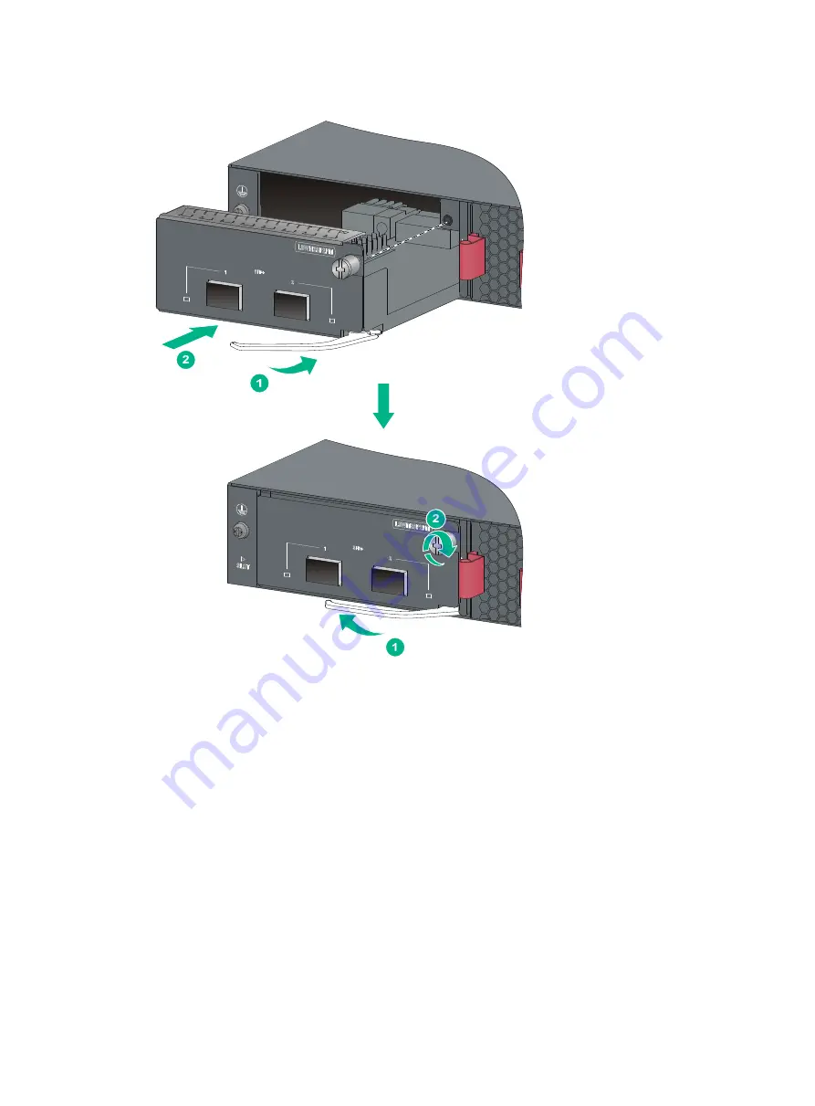
Figure 32 Installing an interface card with an ejector lever 


Removing an interface card 

1. 

Wear an ESD wrist strap and make sure it makes good skin contact and is reliably grounded. 

2. 

Use a Phillips screwdriver to completely loosen the captive screw on the interface card. 

3. 

Rotate rightward the ejector lever on the interface card. 

4. 

Pull the interface card out of the chassis gently along the guide rails. 

Verifying the installation 

After you complete the installation, verify that:  


There is enough space for heat dissipation around the switch, and the rack or workbench is 
stable.  


The grounding cable is securely connected. 


The correct power source is used.  

Содержание flexnetwork 5510 hi series

Страница 1: ...HPE FlexNetwork 5510 HI Switch Series Installation Guide Part number 5200 0020b Document version 6W101 20160930 ...

Страница 2: ...nd 12 212 Commercial Computer Software Computer Software Documentation and Technical Data for Commercial Items are licensed to the U S Government under vendor s standard commercial license Links to third party websites take you outside the Hewlett Packard Enterprise website Hewlett Packard Enterprise has no control over and is not responsible for information outside the Hewlett Packard Enterprise ...

Страница 3: ...G544A JG545A power supply 20 Removing a PSR720 56A PSR1110 56A JG544A JG545A power supply 21 Connecting the power cord 22 Connecting the PSR150 D PSR150 D1 JD366A JD366B power supply 23 Connecting the PSR720 56A JG544A PSR1110 56A JG545A PSR150 A JD362A PSR150 A1 JD362B power supply 23 Installing removing an interface card 24 Installing an interface card 24 Removing an interface card 26 Verifying ...

Страница 4: ...B port 55 10 100 1000Base T autosensing Ethernet port 56 100 1000Base X SFP port 56 SFP port 57 QSFP port 59 Combo interface 61 LEDs 62 System status LED 62 Power supply status LED 62 LED for the port LED mode MODE 62 10 100 1000Base T autosensing Ethernet port LED 63 100 1000Base X SFP port LED 217H63 89HSFP port LED 218H64 90HManagement Ethernet port LEDs 219H64 91HInterface card status LED 220H...

Страница 5: ...iii Index 72 ...

Страница 6: ...pply PSR720 56A Interface cards JH155A HPE 5510 2 port QSFP Module LSWM2QP2P JH156A HPE 5130 5510 10GBASE T 2 port Module LSWM2XGT2PM JH157A HPE 5130 5510 10GbE SFP 2 port Module LSWM2SP2PM For regulatory identification purposes the HPE 5510 HI switches are assigned regulatory model numbers RMNs which are listed in the following table These regulatory numbers should not be confused with the market...

Страница 7: ...t air flows into the switch from the cold aisle and exhausts to the hot aisle Identify the airflow designs of neighboring devices and prevent hot air flowing out of the neighboring device from entering the device The rack is sturdy enough to support the switch and its accessories The rack or workbench is reliably grounded To ensure correct operation and long service life of your switch install it ...

Страница 8: ...Inductance coupling Electromagnetic wave radiation Common impedance including the grounding system coupling To prevent EMI use the following guidelines If AC power is used use a single phase three wire power receptacle with protection earth PE to filter interference from the power grid Keep the switch far away from radio transmitting stations radar stations and high frequency devices Use electroma...

Страница 9: ...crews 1 kit All HPE 5510 HI switches 5190 0297 Rear mounting bracket kit including one pair of mounting brackets and two load bearing screws 1 kit HPE 5510 24G PoE 4SFP 1 slot HI HPE 5510 48G PoE 4SFP 1 slot HI N A M6 screw and floating nut user supplied As required All HPE 5510 HI switches 5185 9292 Grounding cable tin plated at one end and with a ring terminal at the other end 1 HPE 5510 24G 4SF...

Страница 10: ...21 power to port fan tray order as required 2 All HPE 5510 HI switches 5185 9443 5080 0120 DC power cord supplied with the PSR150 D PSR150 D1 JD366A JD366B DC power supply The power cord color code scheme is for illustration only The cable delivered for your country or region might use a different color scheme 1 PSR150 D PSR150 D1 JD366A JD366B DC power supply 5184 6719 Console cable 1 All HPE 551...

Страница 11: ...e 1 Hardware installation flow Ground the switch Install the switch Start Connect power cords Verify the installation Turn on the circuit breaker Select and install power supplies Hot swap power supplies Yes No Operating correctly Turn off the circuit breaker Troubleshoot the switch No Yes Hot swap cards Install interface cards Yes Troubleshoot the switch Yes No End No Operating correctly Install ...

Страница 12: ...id mounting position See Rack mounting by using front mounting brackets Front and rear mounting bracket kits The mounting bracket kit can be installed on the port side or power supply side Install the rear mounting brackets according to the rack depth If the rack depth is in the range of 429 to 595 mm 16 89 to 23 43 in orient the bracket with the wide flange inside the rack If the rack depth is in...

Страница 13: ...10 24G 4SFP HI HPE 5510 48G 4SFP HI HPE 5510 24G PoE 4SFP HI HPE 5510 48G PoE 4SFP HI Front mounting bracket kit Provided Provided Rear mounting bracket kit Not required Provided Chassis rail and slide rail Not required Not required Grounding cable Provided Provided Figure 4 Front mounting bracket kit 1 Hole for attaching the bracket to the switch chassis 2 Hole for attaching the bracket to a rack...

Страница 14: ...ower supply side or mid mounting position HPE 5510 24G PoE 4SFP HI and HPE 5510 48G PoE 4SFP HI switches Mid mounting position 3 Attach the front mounting brackets to the chassis a Unpack the front mounting brackets and the M4 screws supplied with the switch for attaching the brackets to the switch chassis b Align the round holes in the wide flange of one front mounting bracket with the screw hole...

Страница 15: ...on supports the chassis bottom with one hand holds the front part of the chassis with the other hand and pushes the chassis into the rack gently b The other person uses M6 screws and cage nuts user supplied to attach the switch to the rack Figure 9 Mounting the switch in the rack front mounting brackets at the port side ...

Страница 16: ...11 Figure 10 Mounting the switch in the rack front mounting brackets at the power supply side Figure 11 Mounting the switch in the rack front mounting brackets at the mid mounting position ...

Страница 17: ...ckets to the switch chassis b Align the round holes in the wide flange of one front mounting bracket with the screw holes in the port side mounting position on one side of the chassis see Figure 12 c Use M4 screws supplied with the switch to attach the mounting bracket to the chassis d Repeat the proceeding two steps to attach the other mounting bracket to the chassis e Unpack the load bearing scr...

Страница 18: ... the wide flange outside the rack 4 Mount the switch chassis in the rack a One person supports the chassis bottom with one hand holds the front part of the chassis with the other hand and pushes the chassis into the rack gently Make sure the load bearing screws closely contact with the upper edges of the rear mounting brackets as shown in Figure 15 and Figure 16 ...

Страница 19: ...rews user supplied to the front rack posts Tighten the screws and make sure the front and rear mounting brackets have securely attached the switch to the rack Figure 15 Mounting the switch in the rack with the wide flange of the mounting brackets inside the rack Figure 16 Mounting the switch in the rack with the wide flange of the mounting brackets outside the rack ...

Страница 20: ...akage electricity can be safely released to the earth to minimize EMI susceptibility of the switch You can ground the switch in one of the following ways depending on the grounding conditions available at the installation site Grounding the switch with a grounding strip Grounding the switch with a grounding conductor buried in the earth ground Grounding the switch by using the AC power cord NOTE T...

Страница 21: ...ch a ring terminal to the grounding cable a Use a wire stripper to strip 5 mm 0 20 in of insulation off the end of the grounding cable b Slide the heat shrink tubing onto the cable and insert the bare metal part into the end of the ring terminal c Use a crimper to secure the metal part of the cable to the ring terminal d Slide the heat shrink tubing down the cable until the tube covers the joint e...

Страница 22: ... to the post on the grounding strip and use the hex nut to secure the cable to the post Figure 20 Connecting the grounding cable to a grounding strip 1 Grounding post 2 Grounding strip 3 Grounding cable 4 Hex nut Grounding the switch with a grounding conductor buried in the earth ground If the installation site has no grounding strips but earth ground is available hammer a 0 5 m 1 64 ft or longer ...

Страница 23: ...tion room or on the AC transformer side The power cord is securely connected to the power outlet NOTE If the ground contact in the power outlet is not connected to the ground report the problem and reconstruct the grounding system As a best practice to guarantee the grounding effect use the grounding cable provided with the switch to connect to the grounding strip in the equipment room Installing ...

Страница 24: ...es the PSR150 A1 JD362B power supply as an example To install a power supply 1 Wear an ESD wrist strap and make sure it makes good skin contact and is reliably grounded 2 Remove the filler panel from the target power supply slot as follows a Remove the screws on the filler panel b Use a flathead screwdriver to remove the filler panel Figure 24 Removing the filler panel 3 Unpack the power supply an...

Страница 25: ...ndle of the power supply with one hand and pull it out a little support the bottom with the other hand and pull the power supply slowly along the guide rails out of the slot Put away the removed power supply in an antistatic bag or the power supply package bag for future use 5 Install the filler panel to prevent dust and ensure good ventilation if no power supply is installed in the slot Installin...

Страница 26: ...until you hear that the latch of the power supply clicks into the slot When you insert the power supply into the slot you can do that through slight inertia so that the terminals of the power supply can have good contact with the backplane The PSR1110 56A JG545A power supply adds 64 mm 2 52 in to the depth of the switch as shown in Figure 27 5 Install the filler panel over the empty power supply s...

Страница 27: ...ly Connecting the power cord CAUTION The AC power cord for the PSR150 A PSR150 A1 JD362A JD362B uses C13 connector while the AC power cord for the PSR720 56A JG544A PSR1110 56A JG545A uses high temperature C15 connector Do not mix them Provide a circuit breaker for each power supply and make sure the circuit breaker is off before installation Table 7 Power cord connection procedures at a glance Po...

Страница 28: ...nd the DC power receptacle are foolproof Make sure the connector is correctly oriented 3 Use a flat blade screwdriver to fasten the two screws on the DC plug to secure the plug to the DC receptacle see callout 2 in Figure 29 4 Connect the other ends of the wires to the 48 VDC power source wiring terminals with the negative wire or L to the negative terminal and the positive wire or M N to the posi...

Страница 29: ... the installation or removal procedure Install a filler panel over an empty interface card slot The switch has an interface card slot and supports hot swapping of an interface card For the interface cards available for the switches see Appendix B FRUs and compatibility matrixes This section uses the LSWM2SP2PM interface card as an example to describe the procedures of installing and removing an in...

Страница 30: ...nal Rotate out the ejector lever 5 Gently push the interface card into the slot along the guide rails until the interface card has good contact with the switch chassis 6 Optional Rotate in the ejector lever 7 Tighten the captive screws with a Phillips screwdriver to secure the interface card in the slot ...

Страница 31: ... loosen the captive screw on the interface card 3 Rotate rightward the ejector lever on the interface card 4 Pull the interface card out of the chassis gently along the guide rails Verifying the installation After you complete the installation verify that There is enough space for heat dissipation around the switch and the rack or workbench is stable The grounding cable is securely connected The c...

Страница 32: ... correctly connected All the interface cables are cabled indoors If any cable is routed outdoors verify that the socket strip with lightning protection and lightning arresters for network ports have been correctly connected ...

Страница 33: ... console port takes effect if you connect both the serial console port and mini USB console port Figure 33 Connecting the console port to a PC Connecting the console cable A console cable is an 8 core shielded cable with a crimped RJ 45 connector at one end for connecting to the console port of the switch and a DB 9 female connector at the other end for connecting to the serial port on the console...

Страница 34: ...SB Type B connector at one end to connect to the Mini USB console port of the switch and a standard USB Type A connector at the other end to connect to the USB port on the PC To connect to the PC through the Mini USB console cable 1 Connect the standard USB Type A connector to the USB port of the PC 2 Connect the Mini USB Type B connector to the Mini USB console port of the switch 3 Click the foll...

Страница 35: ...30 Figure 35 Device Driver Installation Wizard 6 Click Continue Anyway if the following dialog box appears Figure 36 Software Installation 7 Click Finish ...

Страница 36: ...required terminal settings Bits per second 9 600 Data bits 8 Parity None Stop bits 1 Flow control None Powering on the switch Before powering on the switch verify that the following conditions are met The power cord is correctly connected The input power voltage meets the requirement of the switch The console cable is correctly connected The PC has started and its serial port settings are consiste...

Страница 37: ... software matching release notes for the device After the startup completes you can access the CLI to configure the switch For more information about the configuration commands and CLI see HPE 5510 HI Switch Series Configuration Guides and HPE 5510 HI Switch Series Command References ...

Страница 38: ...8 IRF fabric setup flowchart To set up an IRF fabric Step Description 1 Plan IRF fabric setup Plan the installation site and IRF fabric setup parameters Planning IRF fabric size and the installation site Identifying the master switch and planning IRF member IDs Planning IRF topology and connections Identifying physical IRF ports on the member switches Planning the cabling scheme 2 Install IRF memb...

Страница 39: ...c equals the total switching capacities of all member switches Plan the installation site depending on your network solution as follows Place all IRF member switches in one rack for centralized high density access Distribute the IRF member switches in different racks to implement the ToR access solution for a data center NOTE For the maximum IRF member devices supported by the HPE 5510 HI see the ...

Страница 40: ...RF member switches you must connect the physical ports of IRF port 1 on one switch to the physical ports of IRF port 2 on the other switch As a best practice to avoid loop topology first complete IRF configuration and then connect the IRF member switches The HPE 5510 HI switches can provide 10 GE IRF connections through SFP ports and 40 GE IRF connections through QSFP ports and you can bind severa...

Страница 41: ... IRF member switches If the IRF member switches are far away from one another choose the SFP QSFP transceiver modules with optical fibers If the IRF member switches are all in one equipment room choose SFP QSFP DAC cables For more information about SFP QSFP DAC cables and SFP QSFP transceiver modules see Appendix C Ports and LEDs The following subsections describe several HPE recommended IRF conne...

Страница 42: ...37 Figure 41 Connecting the switches in one rack ...

Страница 43: ... switches Assign the master switch higher member priority than any other switch Bind physical ports to IRF port 1 on one switch and to IRF port 2 on the other switch You can perform IRF port binding before or after connecting IRF physical ports depending on the software release To bind a port on an interface card to an IRF port you must install the interface card first For the interface card insta...

Страница 44: ...e network management station See HPE 5510 HI Switch Series Fundamentals Configuration Guide 4 Verify that you can manage all member switches as if they were one node 5 Display the running status of the IRF fabric by using the commands in Table 10 Table 10 Displaying and maintaining IRF configuration and running status Task Command Display information about the IRF fabric display irf Display all me...

Страница 45: ...e power source meets the requirement c Verify that the operating temperature of the switch is in the acceptable range and the power supply has good ventilation d If the problem persists contact HPE Support To replace a hot swappable power supply see Installing removing a power supply Fan tray failure WARNING Do not power on the switch when the switch does not have a fan tray or has only one fan tr...

Страница 46: ...ontact and is reliably grounded 2 Grasp the two handles of the fan tray as shown by callout 1 in Figure 44 and pull out the fan tray slowly along the guide rails 3 Put the removed fan tray in an antistatic bag Figure 44 Removing a fan tray Installing a fan tray CAUTION To prevent damage to the fan tray or the connectors on the backplane insert the fan tray gently If you encounter a hard resistance...

Страница 47: ...to use the same air flow direction as the fan tray If the switch uses a different air flow direction the system outputs traps and logs to notify you to replace the fan tray Configuration terminal display problems No display Symptom The PC displays nothing when the switch is powered on Solution To resolve the problem 1 Verify that the power supply is supplying power to the switch 2 Verify that the ...

Страница 48: ...43 1 Verify that the following settings are configured for the terminal Baud rate 9 600 Data bits 8 Parity None Stop bits 1 Flow control None 2 If the problem persists contact HPE Support ...

Страница 49: ... status LED PWR2 15 Power supply 1 status LED PWR1 16 SFP port LED 17 Management Ethernet port LED Figure 47 HPE 5510 24G SFP 4SFP HI rear panel 1 Grounding screw 2 Interface card optional 3 Fan tray 1 4 Fan tray 2 5 Power supply 1 6 Power supply 2 optional The HPE 5510 24G SFP 4SFP HI switch comes with power supply slot 1 empty and power supply slot 2 installed with a filler panel You can install...

Страница 50: ... supply 1 status LED PWR1 14 SFP port LED 15 Management Ethernet port LED Figure 49 HPE 5510 24G 4SFP HI rear panel 1 Grounding screw 2 Interface card optional 3 Fan tray 1 4 Fan tray 2 5 Power supply 1 6 Power supply 2 optional The HPE 5510 24G 4SFP HI switch comes with power supply slot 1 empty and power supply slot 2 installed with a filler panel You can install one or two power supplies for th...

Страница 51: ... 1 4 Fan tray 2 5 Power supply 1 6 Power supply 2 optional The HPE 5510 24G PoE 4SFP HI switch comes with power supply slot 1 empty and power supply slot 2 installed with a filler panel You can install one or two power supplies for the switch as required In this figure two PSR720 56A JG544A AC power supplies are installed in the power supply slots For more information about installing and removing...

Страница 52: ... 4 Fan tray 2 5 Power supply 1 6 Power supply 2 optional The HPE 5510 48G 4SFP HI switch comes with power supply slot 1 empty and power supply slot 2 installed with a filler panel You can install one or two power supplies for the switch as required In this figure two PSR150 A1 JD362B AC power supplies are installed in the power supply slots For more information about installing and removing a powe...

Страница 53: ... 1 4 Fan tray 2 5 Power supply 1 6 Power supply 2 optional The HPE 5510 48G PoE 4SFP HI switch comes with power supply slot 1 empty and power supply slot 2 installed with a filler panel You can install one or two power supplies for the switch as required In this figure two PSR720 56A JG544A AC power supplies are installed in the power supply slots For more information about installing and removing...

Страница 54: ...sion interface card slots 1 on the rear panel 1 on the rear panel 1 on the rear panel Power supply slots 2 on the rear panel 2 on the rear panel 2 on the rear panel Fan tray slots 2 on the rear panel 2 on the rear panel 2 on the rear panel Input voltage AC input Rated voltage range 100 VAC to 240 VAC 50 Hz or 60 Hz Max voltage range 90 VAC to 264 VAC 47 Hz to 63 Hz DC input Rated voltage range 48 ...

Страница 55: ...PE 5510 48G PoE 4SFP HI Dimensions H W D 43 6 440 460 mm 1 72 17 32 18 11 in 43 6 440 460 mm 1 72 17 32 18 11 in Weight 10 kg 22 05 lb 10 kg 22 05 lb Console ports 1 Mini USB console port 1 serial console port Only the Mini USB console port takes effect when you connect both ports USB ports 1 1 Management Ethernet ports 1 1 SFP ports 4 4 10 100 1000Base T autosensing Ethernet ports 24 48 Interface...

Страница 56: ...idity 5 to 95 noncondensing Fire resistance compliance UL60950 1 EN60950 1 IEC60950 1 GB4943 The following table describes PoE power capacity for the HPE 5510 24G PoE 4SFP HI and HPE 5510 48G PoE 4SFP HI switches Power supply configuration HPE 5510 24G PoE 4SFP HI HPE 5510 48G PoE 4SFP HI Total PoE power capacity Max PoE power capacity per port Total PoE power capacity Max PoE power capacity per p...

Страница 57: ...e sequence number and vendor of the power supplies you have installed on the device You can install one power supply or two power supplies for redundancy on the HPE 5510 24G 4SFP HI HPE 5510 24G SFP 4SFP HI and HPE 5510 48G 4SFP HI switches These switches support mix of an AC power supply and a DC power supply You can install one power supply or two power supplies for redundancy on the HPE 5510 24...

Страница 58: ...tput power 1110 W HPE PSR1110 56A Power Supply User Guide NOTE The PSR1110 56A JG545A power supply adds 64 mm 2 52 in to the depth of the switch including the depth of the power supply handle Hot swappable interface cards The switch provides an interface card slot at the rear The following table describes the interface cards available for the switch Card model Port type and quantity Available tran...

Страница 59: ...the LSWM2XGT2PM interface cards follow these guidelines Use Category 6A or above cables and connectors The max transmission distance varies by cable type Category 6 UTP 55 m 180 45 ft Category 6 STP 100 m 328 084 ft no interference Category 6 SFTP 100 m 328 084 ft Category 6A and above twisted pair 100 m 328 084 ft Do not bundle cables in their first 20 m 65 62 ft Separate power cords and twisted ...

Страница 60: ...ment station for loading and debugging software or remote management Table 14 Management Ethernet port specifications Item Specification Connector type RJ 45 Connector quantity 1 Port transmission rate 10 100 1000 Mbps half full duplex Transmission medium and max transmission distance 100 m 328 08 ft over category 5 twisted pair cable Functions and services Switch software and Boot ROM upgrade net...

Страница 61: ...odules in Table 16 and the 1000 Mbps SFP transceiver modules in Table 17 in the SFP ports Table 16 100 Mbps SFP transceiver modules available for the 100 1000 Base X SFP ports Produc t code HPE description Central wavelengt h nm Connector Fiber diameter µm Max transmissio n distance JD102B HPE X115 100M SFP LC FX Transceiver 1310 LC Multi mode 50 125 2 km 1 24 miles Multi mode 62 5 125 JD120B HPE ...

Страница 62: ...Mbps SFP transceiver modules available for the SFP ports Produ ct code HPE description Central wavelengt h nm Connecto r Cable fiber diameter µm Modal bandwidth MHz km Max transmissio n distance JD118B HPE X120 1G SFP LC SX Transceiver 850 LC Multi mode 50 125 500 550 m 1804 46 ft 400 500 m 1640 42 ft Multi mode 62 5 125 200 275 m 902 23 ft 160 220 m 721 78 ft JD119B HPE X120 1G SFP LC LX Transcei...

Страница 63: ...Transceiver 850 LC Multi mode 50 125 2000 300 m 984 25 ft 500 82 m 269 03 ft 400 66 m 216 54 ft Multi mode 62 5 125 200 33 m 108 27 ft 160 26 m 85 30 ft JD093B HPE X130 10G SFP LC LRM Transceiver 1310 LC Multi mode 50 125 1500 220 m 721 78 ft 500 400 100 m 328 08 ft Multi mode 62 5 125 200 220 m 721 78 ft 160 JD094B HPE X130 10G SFP LC LR Transceiver 1310 LC Single mode 9 125 N A 10 km 6 21 miles ...

Страница 64: ...d SFP DAC cables available for the switch are subject to change over time For the most up to date list of SFP SFP transceiver modules and SFP DAC cables consult your HPE sales representative or technical support engineer For the specifications for the HPE SFP SFP transceiver modules and SFP DAC cables see HPE Comware Based Devices Transceiver Modules User Guide QSFP port The LSWM2QP2P interface ca...

Страница 65: ...00 150 m 492 12 ft JG325B HPE X140 40G QSFP MPO SR4 Transceiver 850 MPO PC polished 12 fiber 50 125 2000 100 m 328 08 ft 4700 150 m 492 12 ft Table 21 QSFP DAC cables available for the QSFP ports Product code HPE description Max transmission distance JG326A HPE X240 40G QSFP QSFP 1m DAC Cable 1 m 3 28 ft JG327A HPE X240 40G QSFP QSFP 3m DAC Cable 3 m 9 84 ft JG328A HPE X240 40G QSFP QSFP 5m DAC Ca...

Страница 66: ...or the interface cards contact HPE Support or marketing staff You can use a HPE X140 40G QSFP MPO SR4 Transceiver or HPE X140 40G QSFP MPO MM 850nm CSR4 300m Transceiver to connect a QSFP port to four SFP ports The QSFP transceiver module and SFP transceiver modules to be connected must be the same in specifications including central wavelength and fiber type For more information about HPE QSFP tr...

Страница 67: ...alled in power supply slot 1 but the power supply has failed or no power is input to the power supply Off No power supply is installed in power supply slot 1 PWR2 Steady green A power supply is installed in power supply slot 2 and the power supply is outputting power correctly Steady yellow A power supply is installed in power supply slot 2 but the power supply has failed or no power is input to t...

Страница 68: ...llow The port is operating at 10 100 Mbps Flashing yellow The port is sending or receiving data at 10 100 Mbps Flashing yellow 3 Hz POST has failed on the port Off No link is present on the port Flashing green 1 Hz PoE mode available only for HPE 5510 24G PoE 4SFP HI and HPE 5510 48G PoE 4SFP HI switches Steady green PoE power supply is normal Flashing green 3 Hz The device attached to the port re...

Страница 69: ...ndicate the IRF member ID of the switch For example if the LEDs for ports 1 to 5 are steady green and the other port LEDs are off the IRF member ID of the switch is 5 SFP port LED Table 28 SFP port LED description SFP port LED status Description Steady green A link is present on the port and the port is operating at 10 Gbps Flashing green The port is sending or receiving data at 10 Gbps Steady yel...

Страница 70: ...The switch does not support the card model or the card has failed Off The interface card slot is empty Fan tray status LED on the fan tray Each fan tray has a fan tray status LED to indicate its operating status Table 31 Fan tray status LED description Status Description Steady yellow The fan tray is operating correctly Flashing 1 Hz A problem has occurred on the fan tray Off The fan tray is not s...

Страница 71: ...allation site for the switch When the fan trays are operating ambient air flows in through the air vents in the port side panel and in the switch sides circulates through the chassis and the power supplies and exhausts through the air vents in the fan tray and power supply panels as shown in Figure 59 Figure 59 Airflow through the HPE 5510 48G 4SFP 1 slot HI switch IMPORTANT The chassis and the po...

Страница 72: ...st one x y Asterisk marked square brackets enclose optional syntax choices separated by vertical bars from which you select one choice multiple choices or none 1 n The argument or keyword and argument combination before the ampersand sign can be entered 1 to n times A line that starts with a pound sign is comments GUI conventions Convention Description Boldface Window names button names field name...

Страница 73: ... Represents an access controller a unified wired WLAN module or the access controller engine on a unified wired WLAN switch Represents an access point Represents a wireless terminator unit Represents a wireless terminator Represents a mesh access point Represents omnidirectional signals Represents directional signals Represents a security product such as a firewall UTM multiservice security gatewa...

Страница 74: ...s provide a mechanism for accessing software updates through the product interface Review your product documentation to identify the recommended software update method To download product updates go to either of the following Hewlett Packard Enterprise Support Center Get connected with updates page www hpe com support e updates Software Depot website www hpe com support softwaredepot To view and u...

Страница 75: ...r self repair CSR programs allow you to repair your product If a CSR part needs to be replaced it will be shipped directly to you so that you can install it at your convenience Some parts do not qualify for CSR Your Hewlett Packard Enterprise authorized service provider will determine whether a repair can be accomplished by CSR For more information about CSR contact your local service provider or ...

Страница 76: ...umber edition and publication date located on the front cover of the document For online help content include the product name product version help edition and publication date located on the legal notices page ...

Страница 77: ... 28 first time switch access 28 IRF member switches in a ToR solution 38 IRF member switches in one rack 36 IRF physical ports 38 planning IRF connections 35 power cord 22 PSR150 D1 JD366B 23 PSR720 56A JG544A PSR1110 56A JG545A PSR150 A1 JD362B 23 USB mini console cable 29 console connecting cable 28 connecting USB mini cable 29 port technical specifications 55 D data bits parameter 31 device tro...

Страница 78: ...ing PSR720 56A JG544A PSR1110 56A JG545A PSR150 A1 JD362B 23 console port technical specifications 55 fan tray status LED 65 grounding switch 15 grounding switch through AC power cord 18 grounding switch with a grounding conductor buried in the earth ground 17 grounding switch with grounding strip 15 interface card installation 24 24 interface card port status LED 65 interface card removal 26 inte...

Страница 79: ...anning member IDs 34 planning size 34 planning topology 35 setting up 33 setup flowchart 33 verify the IRF fabric setup 39 40 L LED 10 100 1000 Base T autosensing Ethernet port 63 fan tray status LED 65 interface card port status 65 interface card status 65 management Ethernet port 64 port mode 62 power supply input status 65 power supply output status 65 power supply status 62 SFP port 64 system ...

Страница 80: ...stalling PSR150 JD362A JD362B JD366A or JD366B power supply 19 installing PSR720 56A PSR1110 56A JG544A JG545A power supply 20 installing switch 1 6 installing switch in 19 inch rack 7 mounting switch on workbench 15 planning IRF connections 35 planning IRF fabric installation site 34 planning IRF member IDs 34 planning IRF topology 35 rack mounting by using front and rear mounting brackets on 19 ...

Страница 81: ...tifying IRF master switch 34 identifying IRF member switch physical ports 36 installation 1 6 LEDs 55 planning IRF cabling scheme 36 36 planning IRF member IDs 34 ports 55 powering on 31 setting configuration environment 28 setting terminal parameters 31 setting up IRF fabric 33 technical specifications 44 verifying installation 26 workbench mounting switch 15 system administration troubleshooting...

Страница 82: ...ay problems 42 fan failure 40 garbled display 42 no display 42 power supply failure 40 U USB port 55 V verify the IRF fabric setup 39 40 verifying IRF fabric setup 39 40 switch installation 26 VT100 31 W workbench mounting switch 15 ...

Отзывы: