3.
Remove the following screws that secure the bottom cover to the computer:
(1)
: 2 Phillips PM2.0×4.0 screws from the hard drive bay
(2)
: 3 Phillips PM2.0×3.0 screws from the optical drive bay
(3)
: 2 Torx PM2.5×10.0 screws near the docking connector
4.
Remove the 4 Torx PM2.5×6.0 screws from the rear of the computer.
Component replacement procedures
99
Содержание EliteBook 8560p
Страница 1: ...HP EliteBook 8560p Notebook PC HP ProBook 6560b Notebook PC Maintenance and Service Guide ...
Страница 4: ...iv Safety warning notice ...
Страница 8: ...viii ...
Страница 35: ...Computer major components Computer major components 27 ...
Страница 43: ...Display components Display components 35 ...
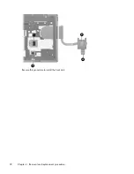
Страница 100: ...Reverse this procedure to install the heat sink 92 Chapter 4 Removal and replacement procedures ...


