HP D5970A - NetServer - LCII Скачать руководство пользователя страница 175

167

A Specifications

Power Requirements

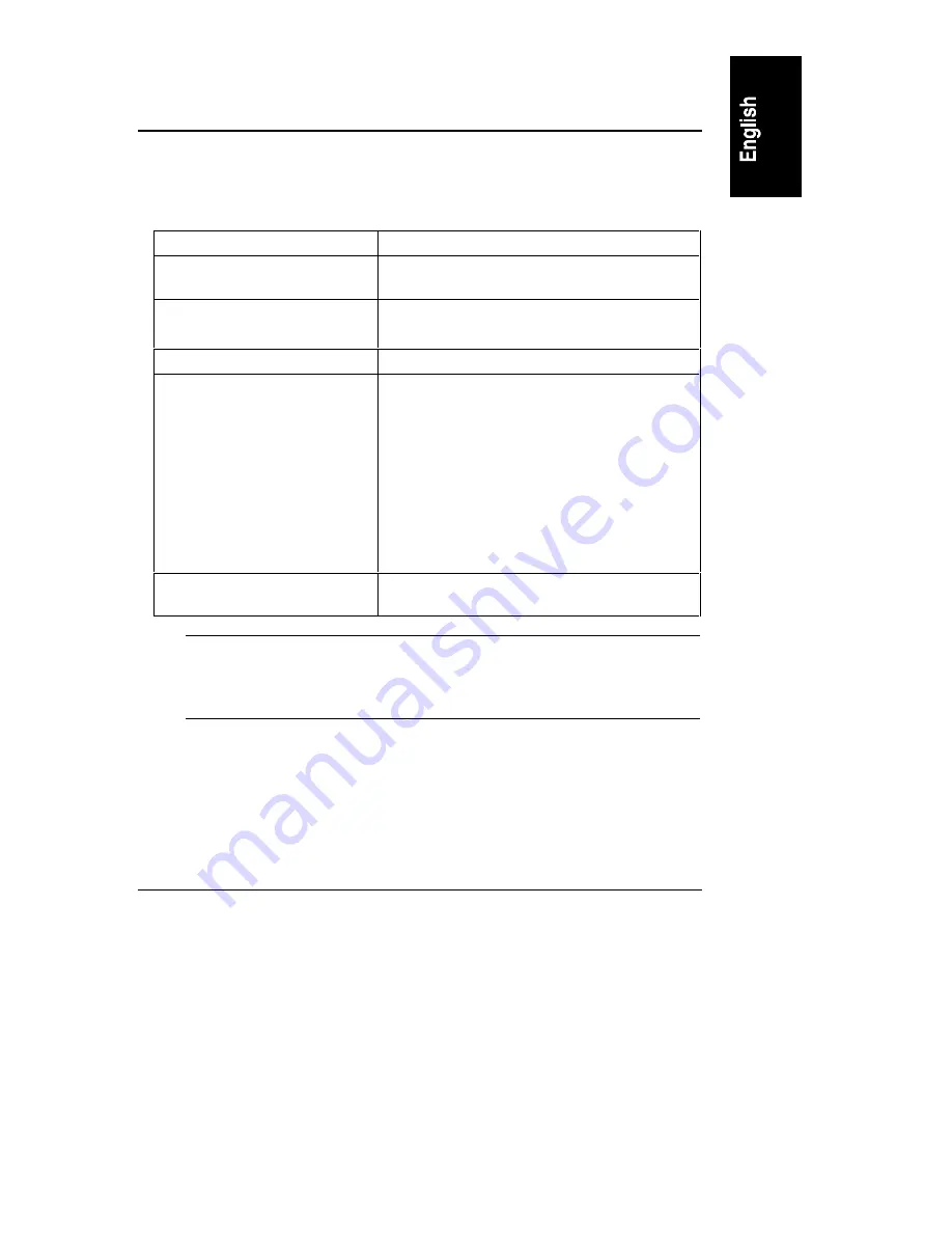
Table A-1. Power Requirements

Voltage and frequency

200-240 VAC; 50/60 Hz

Maximum continuous power
input

1100 W Maximum (8-CPU configuration)

Operating Current

5.6 AMPs Maximum at 200/208 Volts AC

4.9 AMPs Maximum at 230/240 Volts AC

Maximum inrush current

150 AMPs for 4 ms

Delayed action circuit breaker
recommended

North America: a 20 A minimum circuit is to be
used with one NEMA AB1 class 14B breaker
for each 16 A power distribution unit (PDU) that
is connected to an HP NetServer LXr 8500.

Europe (single server in a rack): use a 16
A-minimum circuit with one IEC MCB C-type
breaker for each 16 AMP PDU.

Europe (multiple servers in a rack): use a
16-amp-minimum circuit with one IEC MCB
D-type breaker for each 16 AMP PDU.

Power availability

1500 DC watts continuous (2 power supplies
minimum)

NOTE

Some local codes do allow a 16-amp device to be connected to
a 16-amp service. Consult a qualified electrician or local
regulatory authority before beginning electrical site
preparation.

Содержание D5970A - NetServer - LCII

Страница 1: ...HP NetServer LXr 8500 Installation Guide HP Part Number D7054 90007 Printed September 1999 ...

Страница 2: ...opied reproduced or translated to another language without the prior written consent of Hewlett Packard Company Windows NT and Windows 95 are registered trademarks of Microsoft in the U S and other countries Symbios is a registered trademark of LSI Logic Corp Torx is a registered trademark of CamCar Textron Inc Tinnerman is a registered trademark of Eaton Tinnerman Compuserve is a U S trademark of...

Страница 3: ...ontrols and Indicators 14 Indicators and Controls Behind the Front Bezel 14 Fan Indicators 15 Applying Power to the HP NetServer 16 Powering Up the HP NetServer 16 Powering Down the HP NetServer 17 Connecting AC Power to Multiple Server Configurations 17 Sleep States ACPI 17 Viewing Information on the Control Panel Display 19 Main Menu 20 HW Sys Info Hardware System Information Menu 21 FW Info Fir...

Страница 4: ...xternal SCSI Devices 47 5 Installing Additional Memory 49 Introduction 49 Required Tools 49 Memory Configuration Guidelines 49 Installing Additional Memory 52 Removing a DIMM 58 6 Installing Additional Boards 61 Introduction 61 Tested PCI Boards 61 Tools Required 61 Remote Control Card 62 IRQ Settings 62 Boot Priority 62 I O Baseboard Slots 64 Installing Accessory Boards 65 PCI Hot Plug Boards 72 ...

Страница 5: ...Monitor Keyboard Mouse and UPS 107 Introduction 107 Connecting the Monitor Keyboard Mouse and UPS 107 10Configuring the HP NetServer 109 Introduction 109 HP NetServer Navigator CD ROM 109 Contents of the HP NetServer Navigator CD ROM 109 Obtaining the HP NetServer Navigator CD ROM Release History 109 Obtaining Up to Date Configuration Details 111 Running Configuration Assistant and Installation As...

Страница 6: ...oting Tools 133 Common Installation Problems 134 Troubleshooting Sequence 134 If the HP NetServer Will Not Power On 136 If the HP NetServer Powers On but Fails POST Power On Self Test 136 If the HP NetServer Passes POST but Will Not Function 137 If the HP NetServer Passes POST but Shuts Down While Booting 138 If the HP NetServer Passes POST but a Processor is disabled 138 Error Codes and Messages ...

Страница 7: ... B Regulatory Information 173 Regulatory Notices Electromagnetic Compliance 173 Notice for United States 173 Notice for Canada Industry Canada 174 Notice for Japan 174 Notice for Korea 175 Notice for Taiwan 175 Declaration of Conformity US EU Australia 176 Regulatory Notices Product Safety 177 CD ROM and Laser Safety Statements 177 Battery Statements 179 Power Line Harmonic Statement 180 Noise and...

Страница 8: ......

Страница 9: ...t do not apply to you 1 Unpack the contents of the shipping box CAUTION The HP NetServer LXr 8500 weighs approximately 155 pounds fully configured At least two people are required to lift the HP NetServer Failure to observe this warning could result in serious injury or damage to the HP NetServer 2 Verify the contents of the shipping box against the Contents List included with your HP NetServer If...

Страница 10: ... on when and where you plan to complete the installation process Do you plan to install the HP NetServer in a rack now If so install the HP NetServer in the rack Refer to Chapter 8 Rack Mounting the HP NetServer or Chapter 13 Alternative Rack Mounting Connect the monitor keyboard and mouse cables to the HP NetServer Refer to Chapter 9 Connecting the Monitor Keyboard Mouse and UPS Connect mass stor...

Страница 11: ...e HP NetServer 16 Configure the HP NetServer with Configuration Assistant from the HP NetServer Navigator CD ROM using the Express Configuration option Refer to Chapter 10 Configuring the HP NetServer NOTE To fully configure the HP NetServer all the rack components should be cabled and online but not necessarily installed in the rack Use the HP NetServer LXr 8500 Rack Assembly and Cabling Referenc...

Страница 12: ......

Страница 13: ...ntrols and indicators Front panel controls for power reset and Secure Mode LEDs for power and Secure Mode Three status LEDs one red one yellow one green to provide quick information about HP NetServer status A two line LCD display with its own set of window navigation buttons This display provides detailed information about HP NetServer status The following illustration shows the HP NetServer s fr...

Страница 14: ...Power Button Power LED Reset Button Secure Mode Button Secure Mode LED Figure 2 2 Power Reset and Secure Mode Buttons and LEDs NOTE A small protective cover is provided on the HP NetServer s control panel to cover the Power and Reset buttons This cover can prevent someone from accidentally powering down or resetting the HP NetServer during normal operation It can also be easily opened for access t...

Страница 15: ...PI later in this chapter Power On Off Sleep LED This LED glows a steady green when power is On and dark when the HP NetServer is powered Off If the HP NetServer is under ACPI control this LED will flash between green and dark off when in an ACPI sleep state Reset Button This button performs a system reset hard reset or cold boot Secure Mode Button Puts the HP NetServer in the Secure Mode if it is ...

Страница 16: ...formation and more Figure 2 3 shows the LCD display and its navigation buttons For instructions on using this LCD display see Viewing Information on the Control Panel Display later in this chapter Escape Enter Scroll Up One Line Scroll Down One Line Two Line Display Not Used Figure 2 3 Control Panel Display Window and Navigation Buttons NOTE The LCD display can present a custom defined text string...

Страница 17: ... Red LED Yellow LED Green LED Indicates HP NetServer Status Off Off Off Main power is off and the HP NetServer may or may not be on standby power Flashing Off Off Immediate attention required due to a failed component in the HP NetServer The HP NetServer may not be fully operational due to this condition such as POST errors Off Flashing Off Attention required due to a pre failure condition This co...

Страница 18: ...the PCI hold down latch The LEDs are used to indicate the status of each slot and are also visible from the inside the HP NetServer Figure 2 5 shows the rear of the HP NetServer PCI LED Indicators External SCSI Port Serial Parallel Monitor Ports Power Supplies HP TopTools Remote Control Card and Connectors AC Power Inlet 1 2 3 Figure 2 5 Rear Panel of the HP NetServer NOTE You will find informatio...

Страница 19: ...r the LED is dark PRFL Predictive Fail Blinks yellow if the speed of the power supply s internal fan falls below acceptable levels Power supply has not failed but may do so soon FAIL Power Supply Failure Glows steady yellow when power supply fails Blinks yellow when power supply is drawing more current than it should because of a short circuit in the power supply or elsewhere in the HP NetServer I...

Страница 20: ...trip main circuit breakers or UPS breakers Communication Ports Figure 2 7 identifies the ports on the HP NetServer s rear panel Keyboard Mouse Serial Port B Serial Port A LPT1 VGA USB Not Used External SCSI Figure 2 7 Rear Panel Ports NOTE The keyboard and mouse ports are interchangeable and at boot time the I O Riser board automatically detects which device is connected to the port The I O Riser ...

Страница 21: ...ators Amber Power Attention Figure 2 8 PCI LEDs on the Rear Panel Table 2 4 PCI LED Status viewed from rear Amber LED Green LED Status Indicated Off On Power to the slot is on and the slot is operating normally Do not remove the board from the slot On On Power to the slot is on but the slot needs attention Do not remove the board from the slot On Off Power to the slot is off and the slot needs att...

Страница 22: ...front of the chassis contains various controls and indicators that are only visible when the HP NetServer s front bezel is opened or removed The controls and indicators shown in Figure 2 9 are for the HP NetServer s input and storage devices Eject Button Activity LED Eject Button Activity LED Hot Swap Hard Disk Drive Power ON LED Activity LED Flexible Disk Drive CD ROM Drive DAT Tape Drive Status ...

Страница 23: ...uired Pulsing Pulsing Cartridge Loading Unloading Caution cleaning required Flashing at 4 Hz rate Pulsing at 2 Hz rate NOTE For more information on the HP Tape Drive and its error codes refer to the documentation provided with the tape drive or refer to Hewlett Packard s web site at www hp com Refer to Chapter 4 Installing Mass Storage Devices for installation information Fan Indicators The fan in...

Страница 24: ...s ACPI if supported by a compatible NOS Powering Up the HP NetServer 1 Ensure the HP NetServer s power cord is connected to a power source and the PWR light on each of the HP NetServer s power supplies is flashing green See Figure 2 6 2 Verify the LCD window indicates System is powered off or HP NetServer LXr 8500 3 Press the Power button on the front control panel See Figure 2 2 ...

Страница 25: ...P NetServers on one circuit If a power failure occurs and power is restored all the HP NetServers immediately begin to draw inrush current at the same time If the circuit breakers on the incoming power line have insufficient capability the breakers may trip and thus prevent the HP NetServers from powering up If you have prepared your site for the installation of several HP NetServers on one circui...

Страница 26: ...d off To enter a sleep state the HP NetServer must be fully powered on and then the front panel Power On OFF Sleep switch is pressed for less than 4 seconds default To exit a sleep state press the power switch again for less than 4 seconds default and full operation is restored including the LCD display and the power LED l 3rd state is the normal power shutdown All activity stops except the intern...

Страница 27: ...in Table 2 5 are used to make selections and scroll through the windows Table 2 5 Control Panel Display Control Buttons Button Name Description Escape Return to previous menu Enter Select an item from a menu Down Arrow Scroll down one line through the current window or menu Up Arrow Scroll up one line through the current window or menu Left Arrow Not used Right Arrow Not used NOTE The front panel ...

Страница 28: ... and a blinking cursor indicate submenu selections 3 To choose a selection use the arrow buttons to move the cursor to the appropriate line and then press the Enter button The menu selections are HW Sys Info Information on the HP NetServer s hardware configuration FW Info The version numbers of the HP NetServer s firmware HW P N Part number and serial number of the HP NetServer s chassis Event Log...

Страница 29: ...rough the rest of the information A full window of the display would appear as shown below but the actual display is limited to two viewing lines at time HW Sys Info No Of CPUs x x 1 to 8 CPUs CPU speed 500MHz CPU type PIII Xeon LFT CPU1 stepping xx LFT CPU2 stepping xx LFT CPU3 stepping xx LFT CPU4 stepping xx RFT CPU1 stepping xx RFT CPU2 stepping x RFT CPU3 stepping xx RFT CPU4 stepping xx L2 C...

Страница 30: ...x Pxx YYMMDDHHMM NOTE If the HP NetServer cannot detect one of the components in this menu for example the TopTools Remote Control card RCC the word absent appears next to the component in place of a version number Table 2 6 Abbreviations Used in FW Info Menu Abbreviation Definition BMC Baseboard Management Controller on I O baseboard PSC Power Share Controller on front panel board RCC HP TopTools...

Страница 31: ...r s front panel display Event Log 014 POST Error 2 Use the front panel s down arrow button to scroll down through the rest of the entries A sample display appears below EventLog 008 POST Error 007 TempError 006 CPU Failure 005 POST Error 004 Volt Error 003 CPU Failure 002 POST Error 001 System Boot Each line includes a brief summary of a log entry including the log entry number An on a log entry m...

Страница 32: ...one shown below appears on the HP NetServer s front panel display HW P N Chassis P N 2 Use the front panel s down arrow button to scroll down through the rest of the information An example of a full window display appears as shown below HW P N Chassis P N 5555 44444 Chassis S N 5673330142 3 Use the front panel s down arrow key to scroll down through the entire entry 4 Press Escape again to return ...

Страница 33: ...ESC to skip dump Start Dump ESC represents the Escape button 3 To initiate the dump process scroll down to Start Dump and press the Enter button The Enter button can only initiate the dump process when the Start Dump line is visible Once the dump is initiated the following line appears on the HP NetServer s front panel LCD display Dump initiated 4 Press the front panel s Escape button to return to...

Страница 34: ......

Страница 35: ...bezel for mounting For more information refer to the separate rack mounting guide for third party racks It is packed in the accessories tray in the HP NetServer s shipping box 1 To swing open the bezel grasp it by the handle on its right edge and pull it open to the left This exposes the mass storage devices and memory board bays covered 2 To remove the front bezel pull it straight forward off the...

Страница 36: ...he HP NetServer can operate safely when this access panel is removed but only on a temporary basis Refer to Removing the PCI Access Panel later in this chapter Tools Required The following tools are required for extending the chassis out of the rack and for cover removal and installation on the HP NetServer T 15 Torx driver Top Cover and PCI Access Panel l T 25 Torx driver Rack screws Removing the...

Страница 37: ...WARNING Always disconnect the power cord before removing the top cover to avoid exposure to high energy levels that may cause burns when parts are short circuited by metal objects such as tools or jewelry Disconnect any telephone cables to avoid exposure to shock hazard from telephone ringing voltages 4 Remove the bezel from the front of the HP NetServer See Figure 3 1 Refer to Removing and Replac...

Страница 38: ...flanges to the rack front columns CAUTION To prevent damage to cables or a disruption in service due to a disconnection of cables check for short cables at the rear of HP NetServer and disconnect before proceeding 7 Pull the HP NetServer out from the rack on its slides See Figure 3 2 8 Remove the two T 15 Torx screws on the top cover near the front of the chassis See Figure 3 3 9 Slide the top cov...

Страница 39: ... screws 2 B Pull back cover inch Figure 3 3 Removing screws and Sliding the Cover Back 10 Lift off the top cover See Figure 3 4 The hooked edges holding the top cover in place may catch as you lift it up It may help to jiggle the top cover a little as you lift ...

Страница 40: ...ft off the I O cover 11 To access the area under the I O cover use two fingers to grip the finger holes in the cover and then lift it off 12 To re install the I O cover into the I O compartment at its location a Insert the I2 C cable in the cut out opening in the top of the PCI slot dividers as shown in Figure 3 5 b Align the left edge of the I O cover with the PCI slot divider See Figure 3 5 c In...

Страница 41: ...rward until the tabs along its front edge line up with the screw holes on the fan cage 15 Re attach the two T 15 Torx screws to the top cover Removing the PCI Access Panel Use this procedure to gain access to the 10 PCI board slots for accessory board installation or PCI Hot Plug Replacement All 10 slots are PCI Hot Plug capable but the PCI board must have a Hot Plug compliant driver to take advan...

Страница 42: ...ly removing the board Refer to the topic PCI Hot Plug Boards in Chapter 6 Installing Additional Boards 1 To perform this procedure you must have already safely extended the HP NetServer on its slides See Figure 3 2 Refer to Steps 1 7 in Removing the Top Cover earlier in this chapter If necessary skip Steps 1 3 for PCI Hot Plug Replacement CAUTION To prevent damage or unpredictable results do not a...

Страница 43: ...pter 3 Opening and Closing the HP NetServer 35 A Remove screws 2 B Push panel back inch Figure 3 6 Removing the PCI Access Panel s Screws 4 Lift the PCI access panel away from the top cover See Figure 3 7 ...

Страница 44: ...the PCI access panel lower it onto the top cover about inch to the rear of its normally closed position See Figure 3 6 6 Push the PCI access panel forward until the tabs along its front edge line up with the screw holes on the top cover 7 Re attach the two T 15 Torx screws to the top cover Be sure you use the short T 15 Torx screws ...

Страница 45: ...s clamped to the rear of the filler panel inserted in place of the tape drive Required Tools These tools are required for installation of the optional DAT tape drive l Torx T 10 and T 15 drivers Drive Addressing The Hot Swap hard disk drive bays are assigned SCSI IDs 0 and 1 and the embedded controller holds ID 7 The left hot swap bay center is ID 0 by default and the right is ID 1 as you face the...

Страница 46: ...e DR boot image or system configuration data onto the tape as part of the daily backup keeping it current and stored with system backup on tape If a total system failure occurs the system can be recovered by l inserting a current tape l pressing the DAT tape drive s eject button and the HP NetServer s power On button on the front control panel at the same time This initiates the DAT tape drive whi...

Страница 47: ...D Low Voltage Differential channels A and B Channel A controls the HP NetServer s internal hard disk drives Channel B handles the NetServer s external SCSI port The NetServer starts the scan at device ID 0 when scanning each SCSI channel and goes up to ID 15 before starting to scan the other channel 1 IDE CD ROM drive 2 Flexible disk drive 3 Slot P1 4 Slot P2 5 On board SCSI Channel A SCSI device ...

Страница 48: ...e drive on the anti static bag whenever you set it down Hard disk drives are very susceptible to mechanical shock and can be damaged by a drop as short as one quarter of an inch Take care when unpacking and handling the drive If the drop would crack an egg it will damage the drive 1 At the front of the HP NetServer open the bezel Refer to Chapter 3 Opening and Closing the HP NetServer for details ...

Страница 49: ...e 4 1 Hot Swap Drive and Filler Panel 3 On the drive press the locking latch in and pull the ejector handle out as far as it can go easily as shown in Figure 4 2 CAUTION To prevent damage to the ejector handle do not use extreme force when you open it or the handle will snap off ...

Страница 50: ...until you feel the latch click into place Closing the ejector handle engages the drive with the electrical connector in the hot swap mass storage cage and seats the drive 6 If the drive is unseated in the cage after closing the ejector handle repeat Steps 2 5 The handle was probably not pulled out far enough and the locking latch failed to engage the hot swap mass storage cage Removing a Hot Swap ...

Страница 51: ...er connection 4 Wait 30 seconds for the drive to stop spinning and the drive heads to park 5 Use your hand to support the bottom of the drive while you slowly pull the drive straight out and do not allow the drive to fall 6 Place drive in an electrostatically protected container and do not stack drives Installing the Optional Tape Backup DAT Drive If you require the optional tape backup DAT drive ...

Страница 52: ...d with the tape backup DAT drive for any special handling or installation instructions 5 Remove the front bezel from the HP NetServer Refer to Chapter 3 Opening and Closing the HP NetServer 6 Loosen the three thumbscrews from the memory bay cover and remove the cover See Figure 4 4 It may be necessary to lift the LCD display handle to remove the memory bay cover but it is not necessary to remove t...

Страница 53: ...e cover See Figure 4 5 11 Remove the filler panel from the tape drive slot in the peripheral bay See Figure 4 5 12 Remove the two mounting rails connected to the filler panel and save the rails and screws See Figure 4 5 This may require a T 10 Torx driver instead of a T 15 driver 13 Remove the tape drive from the shipping container and its protective bag 14 Remove the mounting bracket hardware ins...

Страница 54: ... 17 To install the peripheral bay and return power to the HP NetServer reverse Steps 1 through 10 and add Steps 18 and 19 CAUTION To prevent damage to the metal EMI clips and copper grounding gasket use caution when inserting the peripheral bay and the memory bay cover 18 Insert the peripheral bay slowly to ensure you engage the center post of the peripheral bay with the memory board guide bracket...

Страница 55: ...connected to the HP NetServer using this external connector but the external SCSI devices must provide the necessary termination at the end of the SCSI chain If no external devices are connected then no termination is required The internal SCSI controller terminates channel B electrically if no external devices are sensed at the connector CAUTION Do not put high voltage differential HVD SCSI devic...

Страница 56: ......

Страница 57: ...iguration DIMMs DIMM Connectors Memory Board Figure 5 1 Memory Board and DIMMs Required Tools The following tools are required for removal and installation of the memory boards and DIMMs An anti static service kit 3M 8501 8502 8503 or equivalent This kit includes a static dissipating work surface a chassis clip lead and a wrist strap Memory Configuration Guidelines These guidelines should be follo...

Страница 58: ...can be placed in any DIMM slot since there are no restrictions l Open slots between DIMMs is permitted See Figure 5 2 l DIMMs can be installed in any order since there are no requirements to load the slots in any specific sequence Dual Memory Boards l If both memory boards are installed the boards must be identically configured l Open slots between DIMMs is also permitted l Mixing DIMM sizes and p...

Страница 59: ...would increase memory capacity to 16 GB 8 GB per memory board NOTE DIMM sizes larger than 256 MB may be available after the initial release of the HP NetServer LXr 8500 Left Board DIMM Size 1 DIMM Size 2 DIMM Size 1 DIMM Size 1 DIMM Size 2 DIMM Size 2 Right Board DIMM Size 1 DIMM Size 2 DIMM Size 1 DIMM Size 2 DIMM Size 1 DIMM Size 2 Shown installed in HP NetServer underside displayed Figure 5 2 D...

Страница 60: ...ing the HP NetServer for details 5 At the front of the HP NetServer locate the LCD display and the memory bay cover just below it See Figure 5 3 On top of the LCD display s housing is a small handle used to raise or lower the LCD display The memory bays are concealed and protected by the memory bay cover 6 Loosen the three captive screws holding the memory bay cover in place See Figure 5 3 7 Pull ...

Страница 61: ...y 53 B Pull up on LCD handle A Loosen captive screws 3 on Memory Bay Cover C Remove Memory Bay Cover Figure 5 3 Gaining Access to the Memory Board Bays 9 Pull open the two retaining latches holding the memory board in place See Figure 5 4 ...

Страница 62: ...y Board 10 Hold the memory board by the corners and carefully pull the board from its slot See Figure 5 4 NOTE If you need to remove both memory boards repeat Steps 2 and 3 for the other board 11 Place the memory board component side up on a firm anti static surface for protection NOTE The component side of the memory board must be face up and rest on a firm surface to apply pressure to the DIMM ...

Страница 63: ... using non HP Buffered SDRAM DIMMs 12 Locate the desired slot for installing the DIMM Refer to Figure 5 2 and the Memory Guidelines earlier in this chapter for possible DIMM locations 13 Remove the DIMM from its container handling the module by its edges See Figure 5 5 Metal Shield over Memory Chips Figure 5 5 DIMM Module NOTE Some of HP s DIMMs will not have the metal shield on the DIMM 14 If nec...

Страница 64: ... The retaining clips grasp the DIMM automatically if it is inserted properly CAUTION Do not rock the SDRAM DIMM into place but apply firm and even pressure If a gap exists between the retaining clips and the DIMM module remove the DIMM and repeat steps 15 19 20 If necessary repeat Steps 12 19 to install all remaining DIMMs for the desired memory configuration including the second memory board NOTE...

Страница 65: ...ory board into either memory bay slot align the memory board with its respective guide rails See Figure 5 7 Ensure the component side DIMMs of the memory board faces down Guide Rails Memory Board Front of HP NetServer Connector Figure 5 7 Replacing the Memory Board 23 Slide the board into the guide rails of the memory bay See Figure 5 7 Ensure the LCD display does not interfere with the right memo...

Страница 66: ...ils 29 Reconnect the power cord and return power to the HP NetServer using the respective NOS instructions Removing a DIMM Use this procedure to remove DIMMs from the HP NetServer s memory boards The HP NetServer must be powered down and the memory board s must be removed from the HP NetServer before removing any DIMMs NOTE If removing DIMMs from a HP NetServer operating with two memory boards ens...

Страница 67: ...rd NOTE Ensure all retaining clips on the memory board are closed before re inserting it into the HP NetServer This includes clips on empty slots as well as those on slots containing DIMMs 7 If necessary remove the other memory board to remove the identical DIMMs on it as well 8 If all DIMMs have been removed follow Steps 22 30 in Installing Additional Memory earlier in this chapter to install the...

Страница 68: ......

Страница 69: ...igator CD ROM Refer also to the Hardware Tested Products link for the HP NetServer LXr 8500 under the HP NetServers Service and Support topic for the specific NOS used in your NetServer at HP s website http www hp com netserver servsup compatibility CAUTION Some accessory board outputs may exceed U S National Electrical code NFPA 70 Class 2 or limited power source limits and must use appropriate i...

Страница 70: ...yond the standard set of 15 since some accessory boards like multi port adapter boards may require more than one IRQ per slot A special hardware feature APIC eliminates interrupt conflicts by providing an expanded set of IRQs with up to four dedicated interrupts for each PCI slot Therefore it is unnecessary to manually assign interrupts for the following NOSs Microsoft NT 4 0 Novell NetWare 5 and ...

Страница 71: ...ip over the onboard SCSI channels and select a different PCI slot when scanning for boot devices For instructions refer to the SCSI Configuration Utility in Chapter 10 Configuring the HP NetServer Table 6 1 HP NetServer Boot Order default Boot Order Component Slot 1 IDE CD ROM drive 2 Flexible disk drive 3 Slot P1 4 Slot P2 5 On board SCSI Channel A 5a SCSI device ID 0 5b SCSI device ID 1 5c SCSI ...

Страница 72: ...6 33 MHz P8 P7 3 3 VDC 66 33 MHz P6 P3 5 VDC 33 MHz P2 P1 5 VDC 33 MHz Remote Control Board must be in slot P2 10 9 8 7 6 5 4 3 2 1 Configuration Switch Block Bus 0 Bus 1 Bus 2 Bus 3 64 bit Default Figure 6 1 HP NetServer I O Baseboard Six PCI slots P1 P6 support full length 32 or 64 bit boards at a clock rate of 33 MHz These slots only support boards with 5 VDC power and Universal boards These sl...

Страница 73: ...d 3 default If a DAC board or a similar type controller is installed additional buses are automatically reassigned up to 6 busses Open Off Shaded rectangle represents the depressed side of the configuration switch Closed On 1 Reserved Open 2 Recovery Boot 3 Reserved 4 Reserved 5 CMOS Clear 6 Password Clear 7 PCI Hot Swap Switch Disable 8 Reserved Front of HP NetServer Figure 6 2 I O Baseboard Conf...

Страница 74: ...de standby current to the HP NetServer until the power cable is disconnected CAUTION Do not attempt to install or remove PCI boards with the HP NetServer in any kind of sleep state or a system crash or hang may occur 3 If required extend the HP NetServer out from the rack on its slides by performing the necessary steps including the safety precautions Refer to Chapter 3 Opening and Closing the HP ...

Страница 75: ...wn Latch The PCI hold down latch is used to keep the PCI boards in place and to activate the PCI slot power switch and PCI LED board 8 Remove the PCI slot cover from the HP NetServer s rear panel before installing the new board into the slot See Figure 6 4 NOTE The PCI slot covers use spring tension and the PCI hold down latch to hold the slot cover board in place instead of a screw commonly used ...

Страница 76: ...talled you must ensure the unused slot has a PCI slot cover installed 9 Open the PCI board guide latch before installing the new PCI board See Figure 6 5 CAUTION Do not bend the PCI board to install it into the slot If the PCI board is full length the PCI board guide latch at the rear of the PCI slot is used to hold the board in place The latch at the top of PCI board guide prevents the board from...

Страница 77: ...prevents its installation remove the handle before installing the board 10 Before installing the PCI board Verify there is no handle attached to it especially if it is a full length board If it has a handle attached remove the handle before installing the board into the slot 11 Align the board with its slot along its full length and position it into the slot See Figure 6 6 12 Push the PCI board do...

Страница 78: ...ing it in from the rear of the HP NetServer until it clicks See Figure 6 7 The PCI hold down latch should click when you push it into place 14 Close the latch on the PCI board guide See Figure 6 7 15 If the installed accessory board requires an external connection or a connection to the I O baseboard ensure the cable is properly attached Refer to the accessory board documentation for connection re...

Страница 79: ...lot will not be powered on when the HP NetServer reboots 16 If the accessory board s installation is complete install the PCI access panel Refer to Chapter 3 Opening and Closing the HP NetServer CAUTION If the Cable Management Arm is not used use caution when sliding the chassis into the rack to prevent damage to cables 17 Slide the chassis back into the rack Refer to Chapter 3 Opening and Closing...

Страница 80: ...tion 21 Restore the HP NetServer to normal operation NOTE To prevent intermittent problems ensure each unused PCI slot has a PCI slot cover in place If a PCI board is removed and a replacement is not re installed you must ensure the unused slot has a PCI slot cover installed PCI Hot Plug Boards The PCI Hot Plug option is Network Operating System NOS dependent To use the Hot Plug option the PCI boa...

Страница 81: ... NOS procedures perform the following steps 1 Insert the HP NetServer Online Documentation CD ROM into a CD ROM drive 2 Select HP NetServers L Series button 3 Scroll down to and select HP NetServer LXr 8500 in the list 4 Select Install 5 Select Installing Accessory Boards 6 Select the appropriate Hot Plug Replacement NOS topic The procedures for powering off on the slot and removing replacing the ...

Страница 82: ......

Страница 83: ...have terminators installed See Tables 7 1 and 7 2 The HP NetServer supports up to eight processor modules with cache sizes of 1 or 2 MB but all processor modules must have the same cache size The processor modules include the 400 and 450 MHz Pentium II Xeon and the 500 and 550 MHz Pentium III Xeon processors Advanced processors will be supported as each one is made available Contact HP or your res...

Страница 84: ...ors The processor boards have the required VRMS installed on the board NOTE Before installing additional processors you must first determine the slot availability for processor installation Refer to Tables 7 1 and 7 2 for processor requirements Table 7 1 Processor Baseboard Configuration 4 way Number of Processors to Install Install in These Carrier Slots Required Terminators for These Carrier Slo...

Страница 85: ...cessor 1 Right Processor 2 Right Processor 3 Right Processor 4 8 Left Processor 1 Left Processor 2 Left Processor 3 Left Processor 4 Right Processor 1 Right Processor 2 Right Processor 3 Right Processor 4 None Both Left and Right Processor Carriers Used Both Cache Coherency filters must be installed Processor Baseboard The HP NetServer s processor baseboard supports two processor carrier boards de...

Страница 86: ...y slots on both processor carrier boards must have a terminator installed See Tables 7 1 and 7 2 and Processor Configuration Guidelines earlier in this chapter for the order of processor placement 4 Way Configuration The four way configuration shown in Figure 7 2 is the minimum standard configuration shipped and is provided with l 1 Processor Module min l 7 Terminators 3 in left carrier and 4 in r...

Страница 87: ...hrough 7 10 show the Processor Tray and its Processor Cage Covers removed for clarity 8 Way Configuration The 8 way configuration uses both left and right processor carrier boards for its processor module minimum 5 and requires both cache coherency filters See Figure 7 3 The cache coherency filters are used effectively when five or more processor modules are installed The cache coherency filters i...

Страница 88: ...ing steps assume the HP NetServer is already in a rack Ensure you unplug power from the HP NetServer before pulling it forward on its slides If you have space in the rack over the HP NetServer you may be able to install remove processor modules without pulling the chassis out of the rack 1 Perform the shutdown procedure listed in Chapter 3 Opening and Closing the HP NetServer for the respective NO...

Страница 89: ...HP NetServer with processors of a different clock speed than previously used you must change the jumper settings on jumper block J6A1 on the processor baseboard See Figures 7 4 and 7 5 5 If necessary change the jumper settings to match the processor speed of all the processor modules in the HP NetServer CAUTION All processors on the baseboard must have the same speed cache size and product number ...

Страница 90: ...ard Jumper Block 2 1 3 5 7 9 11 13 15 16 14 12 10 8 6 4 J61A Jumper Settings for 500 MHz Processors J61A Jumper Settings for 550 MHz Processors 2 1 3 5 7 9 11 13 15 16 14 12 10 8 6 4 2 1 3 5 7 9 11 13 15 16 14 12 10 8 6 4 2 1 3 5 7 11 15 16 12 8 6 4 2 1 3 5 7 11 15 16 12 8 6 4 10 9 14 13 J61A Jumper Settings for 450 MHz Processors 2 1 3 5 7 11 15 16 12 8 6 4 2 1 3 5 7 11 15 16 12 8 6 4 10 9 14 13 ...

Страница 91: ... a grounded unpainted metal surface on the HP NetServer to discharge static electricity Wear a wrist strap and use a static dissipating work surface connected to the chassis when handling components Ensure the metal of the wrist strap contacts your skin 6 Put on the anti static wrist strap and place the anti static mat on a firm surface near the system 7 Connect the strap and mat to an unpainted m...

Страница 92: ... captive screws B Swing cover open to 45 Ο C Lift cover off processor cage Figure 7 6 Opening the Processor Cage 10 At the top of the processor cage remove the existing terminator from the desired slot next available processor slot See Table 7 1 and Figure 7 7 ...

Страница 93: ...ors 85 A Pull up retaining latches B Lift terminator out of slot Figure 7 7 Removing the Terminator 11 Remove the processor module from its sealed bag 12 Install the processor into the next available slot in the processor cage See Figure 7 8 ...

Страница 94: ...Figure 7 8 Installing a Processor 13 Rotate the retaining latches to seat the processor module firmly in the connector 14 Ensure the retaining latches are closed In the closed position the latches should grab the rails on either side of the processor cage while pressing the processor into the slot but there is no noticeable click when this occurs See Figure 7 9 ...

Страница 95: ...s to secure processor Figure 7 9 Retaining Latches in Closed Position 15 Replace the cover on the processor cage a Position the cover tabs into the matching slots on the rear rim of the cage See Figure 7 10 b Lower the cover into place and secure the captive screws ...

Страница 96: ... the HP NetServer 17 Reconnect the power cord 18 Return the HP NetServer to normal operation NOTE You are not required to use the HP NetServer Navigator CD ROM to reconfigure your system after installing the new processor module The HP NetServer detects the additional processors automatically However HP recommends using the HP NetServer Navigator CD ROM to ensure you have the latest drivers and in...

Страница 97: ...k refer to Chapter 13 for instructions If you are mounting the HP NetServer in a non HP rack refer to the separate rack mounting guide for third party racks It is packed in the accessories tray in the HP NetServer s shipping box a b d e Characteristics of System E and System U Racks a 5 Cornered Columns b Full Panel Vent c HP Rack System E or HP Rack System U Name Plate d Numbered EIA Units e Anti...

Страница 98: ...ompletely configured by the vendor before delivery to the customer then mounting the HP NetServer in the rack may be the final step in the installation procedure If the vendor configures the HP NetServer at the customer s site installation of the network operating system and other software may occur after the HP NetServer is mounted in the rack WARNING The HP NetServer weighs over 155 pounds To re...

Страница 99: ...s you mount equipment in the rack ensure you allow enough air flow for safe operation of the equipment The NetServer s fans will only operate correctly if both front and rear doors of the rack allow free air flow perforated openings or are removed Mechanical Loading Uneven mechanical loading within the rack can cause hazardous conditions To prevent this in your installation plans place the heavies...

Страница 100: ...omes with the HP NetServer This template shows you where to mount the nuts on the rack Attaching Rack Nuts to the Rack Use this section to attach the rack nuts to the front and rear columns of the HP System E or HP System U rack The rack nuts are used to hold the HP NetServer s slides in place and to secure the front of the HP NetServer to the rack CAUTION If other rack components are to be mounte...

Страница 101: ...n of 7 EIA units the height required by the HP NetServer 4 Slide the rack nuts onto the column where indicated on the template See Figure 8 2 If you don t have the template Figure 8 3 shows rack nut placement for the front columns Figure 8 2 Placing Rack Nuts on Rack Columns Bottom of Server Fourth Hole From Bottom Sixth Hole From Bottom Ninth Hole From Bottom Seventeenth Hole From Bottom Attach n...

Страница 102: ...Fourth Hole From Bottom Sixth Hole From Bottom represents the EIA unit numbers on the rack columns Figure 8 4 Rack Nut Locations on the Rack s Rear Columns Attaching the Slides to the Rack 1 Pull the anti tip foot forward out of the bottom of the rack See Figure 8 5 for the anti tip foot location 2 Hold a slide in position inside the two left hand rack columns a The mounting flange on each end mus...

Страница 103: ...the screws only loosely at first so the bracket can settle into the lowest possible position b Then tighten the screws until the bracket is held firmly to the column 4 Fasten the slide s rear bracket to the rack nuts on the left rear column a Secure the screws only loosely at first so the bracket can settle into the lowest possible position b Then tighten the screws until the bracket is held firml...

Страница 104: ... on the black handle on each module 3 Then pull the module out of the HP NetServer See Figure 8 6 Figure 8 6 Removing the Power Supply Modules WARNING The HP NetServer weighs more than 155 pounds Removing the power supplies reduces this weight significantly and reduces the likelihood of accidents and improves its balance Re install the power supplies only after the HP NetServer is securely mounted...

Страница 105: ...s anti tip foot forward out of the bottom of the rack to prevent rack instability while mounting the HP NetServer Failure to do so could result in injury and equipment damage See Figure 8 7 2 Pull out both slides until the slide members are fully extended See Figure 8 7 The slides click into position when locked This locked position prevents the slides from moving back into the rack unless the rel...

Страница 106: ...ne other person lift the HP NetServer by its four handles off the floor or pallet 4 Move the HP NetServer between the extended slide members to position the slides underneath the HP NetServer s handles on each side See Figure 8 8 Handles 1 Move NetServer onto slides 2 Fasten slides to NetServer with screws four screws per slide Figure 8 8 Mounting the HP NetServer on the Slides 5 Lower the HP NetS...

Страница 107: ... members 7 Insert the screws 8 into the slides holes to secure the chassis to the slides 8 Use a Torx T 20 driver to remove the screws holding the handles to the HP NetServer See Figure 8 9 9 Take the handles off the HP NetServer and store the handles and screws in a convenient place The handles are re attached when removing the HP NetServer from the rack If transporting the HP NetServer always pa...

Страница 108: ... release latch on each slide and push the HP NetServer into the rack Figure 8 10 Pressing in the Release Latches 11 Verify the HP NetServer slides all the way into the rack before continuing with the procedure CAUTION To prevent a possible system crash when performing a Power Supply Hot Swap do not use older power supplies from the HP NetServer LXr 8000 Use HP NetServer LXr 8500 part number 0950 3...

Страница 109: ...ti tip foot is still extended from the front of the rack A tip over hazard exists so never slide more than one component out of the rack at a time 1 Ensure the HP NetServer LXr 8500 is pushed all the way into the rack 2 At the rear of the HP NetServer place rack nuts on the left column in the 13th and 18th holes above the baseline of the HP NetServer See Figure 8 11 Sixth Hole from Bottom Fourth H...

Страница 110: ...ar column of the rack with the two M 5 pan head T 25 Torx screws included with the Arm See Figure 8 12 6 Extend the HP NetServer out of the rack to ensure the Cable Management Arm moves along with the chassis without binding 7 Plug the HP NetServer s power cable and any available data cables into the back of the HP NetServer NOTE Refer to the HP NetServer LXr 8500 Rack Assembly and Cabling Referen...

Страница 111: ...e HP NetServer before mounting the bezel 1 Place the hinge into the slots on the front of the HP NetServer at the left front edge as shown in Figure 8 13 The two hooks on the rear of the hinge must fit into the two matching holes on the front of the HP NetServer The hooks attach the hinge to the HP NetServer but not securely 2 Swing to left to bring it against front of NetServer 1 Place hinge agai...

Страница 112: ...lign with holes on the HP NetServer itself 2 Tighten screws by inserting driver through access holes in hinge as shown 1 Insert screws into holes through open side of the hinge as shown Figure 8 14 Fastening the Bezel Hinge to the Chassis 4 Use the access holes in the top of the hinge to insert a driver and finish tightening the three screws 5 Attach the bezel latch to the HP NetServer with screws...

Страница 113: ...a Torx T 25 driver Each of the HP NetServer s two front flanges has two slots which should line up with the rack nuts previously mounted on the rack columns 7 Hold the bezel in front of the HP NetServer and line it up with the hinge and bezel latch 8 Press it firmly into place especially at the top left and bottom left corners You should hear several clicks as the bezel snaps into place on the hin...

Страница 114: ... 16 Attaching the Bezel to the HP NetServer Continuing with the Rack Installation Process After you install the HP NetServer in the rack refer to the Rack Installation Road Map to continue with the process of installing and configuring your HP rack system ...

Страница 115: ... and a connector for the video mouse serial 2 parallel and keyboard ports at the rear of the chassis See Figure 9 1 Connecting the Monitor Keyboard Mouse and UPS To connect the peripheral control devices and the UPS to the HP NetServer refer to the following procedure 1 Connect the monitor keyboard and mouse to the HP NetServer using the connections provided on the rear of the chassis See Figure 9...

Страница 116: ...ug the keyboard into the Mouse port if you want or the mouse into the Keyboard port 2 If you have an UPS Uninterruptible Power Supply installed in the rack turn it on 3 Connect the serial cable provided between the UPS and the HP NetServer as specified in the HP NetServer Rack Installation Road Map Refer to the user guide included with the UPS and to the HP NetServer Rack Installation Road Map for...

Страница 117: ...est HP NetServer updates and drivers Contents of the HP NetServer Navigator CD ROM The main menu of the HP Navigator directs you to modules where you can perform configuration tasks or access online system documentation The menu buttons for these modules are as follows Readme File Configuration Assistant and Installation Assistant HP Management Solutions NetServer Utilities User Preferences You ma...

Страница 118: ...n number Release date Part number of the HP NetServer Navigator CD ROM Document Number The Status Report for your specific HP NetServer Navigator CD ROM describes in detail any software updates between this version of the CD ROM and the previous version To obtain a Release History or a Status Report you will need a Document Number Release History Document Number is 6005 Status Report The number is...

Страница 119: ... the power on button 2 Press the CD ROM drive eject button 3 Place the HP NetServer Navigator CD ROM L Series in the drive and press the eject button again to close the drive NOTE Using the low profile CD ROM drive is slightly different than full height units The disk drawer will spring out only part way when you push the eject button You must manually pull the drawer open and manually close it af...

Страница 120: ... the BIOS Before you run Configuration Assistant and Installation Assistant you may need to do one of the following items using the Symbios SCSI Configuration Utility and the Setup Utility BIOS Verify or if required modify SCSI host adapter settings l Use the Symbios Configuration Utility if required to low level format SCSI disks or verify SCSI disk media Running Configuration Assistant and Insta...

Страница 121: ...ft Windows NT Server you will be asked Would you like to use HP s automated mode of NOS installation Select Yes for automated NOS installation Perform an automated NOS installation for first time installation of Novell NetWare IntranetWare or Microsoft Windows NT Server on a factory configured HP NetServer Automated NOS installation will guide you through the NOS installation set up the hard disk ...

Страница 122: ...t from the disk Read the instructions first and then follow them to manually install the NOS View Configuration Advisories Read the configuration advisories and print them if necessary You can change your hardware at this time to conform to the advisories Configure Remote Management This utility configures the Integrated Remote Management device for remote management It enables remote dial up HP N...

Страница 123: ...r Navigator CD ROM By selecting Execute on the Execute Board Utilities screen you can execute these utilities to complete the configuration of the boards Custom Configuration Only select Custom on the Configuration Assistant menu if you are experienced in HP NetServer configuration and have a preferred sequence of steps or if you prefer to configure your system one component at a time In Custom co...

Страница 124: ...ystem resource interrupts I O space allocation Show NOS Installation Instructions Select this option to save a copy of NOS installations instructions to flexible disk and to print them out Replicate Configuration In Replicate configuration mode you can save a copy of your current system configuration or load a previously saved configuration This method saves time when configuring multiple identica...

Страница 125: ...ant guides you through the NOS installation and configures the NOS with the appropriate drivers for the HP bundled configuration Manual NOS Installation Follow the instructions on the screen and the printout of the Network Operating System Installation Instructions HP Management Solutions HP Management Solutions is a comprehensive suite of utilities applications and built in features to manage mul...

Страница 126: ...ty threshold alert and usage tracking View of critical HP NetServer inventory information such as the BIOS version driver and firmware versions PCI slot contents and serial and parallel ports Easy linkage with leading management platforms including HP OpenView Network Node Manager and Workgroup Node Manager Support for DMI 2 0 which provides the same Desktop Management Interface inventory informat...

Страница 127: ...t console redirection of the HP NetServer console Full graphics console redirection of Microsoft Windows NT Servers across the network or over a modem connection using Symantec s pcANYWHERE32 software included with the system See the HP TopTools Remote Control User Guide for details PcANYWHERE32 pcANYWHERE32 is remote controlled graphics redirection software from Symantec Corporation which allows ...

Страница 128: ...formation Allows you to print or view the current system configuration including details of which boards are detected in the HP NetServer and which resources are allocated to the boards Change User Preferences Lets you change the language used by the HP NetServer Navigator CD ROM and the system date and time Setup Utility The HP NetServer has a Setup Utility BIOS in read only memory The utility fe...

Страница 129: ...ver Enables system event logging and sets its logging options Also redirects the console and sets the HP NetServer to re test its processors at boot time Boot Sets the boot device priority boot order for the HP NetServer s internal hard disk drives and for its removable devices It also sets the maximum number of I2 O drives the message timeout multiplier and the pause interval during POST Exit Exi...

Страница 130: ...etServer LXr 8500 to require a password upon booting Further you can have a separate user password and administrator password To configure the HP NetServer to require a boot password 1 Select Security from the Setup menu using the right arrow or left arrow key As soon as you do this the Security menu appears 2 Move to the Password on Boot field using the down arrow key 3 If the entry in this field...

Страница 131: ...ction to allow the user to reset their password if they have forgotten it The selection is titled RMC User Password Reset This can also be done by toggling a switch position 6 in the Configuration Switch Block on the I O baseboard Changing the System Date and Time To change the HP NetServer date and time refer to the following procedure 1 Use the right arrow or left arrow key to select Main from t...

Страница 132: ...ernal Devices You can change the boot priority of the HP NetServer s internal mass storage devices such as the CD ROM the flexible disk drive or other removable device and the hard drives connected to the HP NetServer s internal SCSI To change the boot priority refer to the following procedure NOTE The HP NetServer LXr 8500 provides an additional feature or subset of boot priority that allows flex...

Страница 133: ...rver Online Documentation CD ROM under Configure for more information 8 Use the plus key to move the desired hard drive or DAC to the top of the list NOTE If Multi boot is Enabled default setting and you want the HP NetServer to boot from a specific hard drive you must select the specific hard drive from the list to ensure the HP NetServer will boot from the desired hard drive 9 Press Esc to exit ...

Страница 134: ...10 to save the configuration changes and exit The HP NetServer reboots SCSI Configuration Utility The HP NetServer uses the Symbios Configuration Utility as its SCSI Configuration Utility If you need to verify or modify SCSI host adapter settings low level format SCSI disks or verify SCSI disk media run the Symbios Configuration Utility as follows 1 Turn on or reboot your system 2 During system st...

Страница 135: ...ettings 5 To format a hard disk or change hard disk parameters Select an adapter from the list in the main menu Select Device Selections Select the hard disk to format Select Format menu option For more details including default settings refer to Information Assistant on the HP NetServer Online Documentation CD ROM ...

Страница 136: ......

Страница 137: ...the information you need The following is a brief description of these features To understand how to use each function use the Information Assistant help system Restart from the HP NetServer Online Documentation CD ROM on the NetServer and run Information Assistant or install Information Assistant as an application program on a Windows client machine see the section Installing HP Information Assis...

Страница 138: ...opics For example Jump to other topics Click on hot spots in graphics and text that link to other topics or to more information about the current topic Hot spot text appears as bold green text Identify hot spots on graphics by moving the pointer over the graphic When you point to a hot spot the pointer changes to a hand Return to any previously viewed topic by choosing History from the Topic menu ...

Страница 139: ... copy the data files to your hard disk to improve access time but this could take up a significant amount of disk space Installing from the CD ROM To install Information Assistant onto a Windows PC from the HP NetServer Online Documentation CD ROM perform these steps 1 Turn on your computer and CD ROM drive 2 Run Windows and display the Program Manager 3 Insert the HP NetServer Online Documentatio...

Страница 140: ......

Страница 141: ... switch does NOT turn off the standby power Disconnect the power cord from the HP NetServer before handling components The HP NetServer Navigator CD ROM contains HP NetServer Utilities At the HP NetServer Navigator Main Menu select Access NetServer Utilities to use the following tools HP DiagTools Utility An easy to use hardware diagnostic for NetServer verification burn in and rapid troubleshooti...

Страница 142: ... you have one refer to the HP NetRAID Series User Guide for HP NetRAID and HP NetRAID 1 in Information Assistant For problems with HP TopTools refer to the HP TopTools Administrator Guide on the HP Web Site at http www hp com toptools For general information on management products refer to http www hp com go netserver_mgmt and search for management Common Installation Problems The following sectio...

Страница 143: ...tions one at a time checking its affect on the HP NetServer Unplug the power cord wait 20 seconds plug the power cord in again and restart the HP NetServer l If you suspect a hardware error follow these steps a Log users off the LAN and power down the HP NetServer b Extend the HP NetServer out of the rack and remove the top cover c Simplify the HP NetServer configuration to the minimum required Mo...

Страница 144: ...y You can release the lever and then reset it or remove the power supply out of the HP NetServer 4 If you remove the power supply to reseat it wait 15 seconds before re installing the power supply This prevents tripping the inrush current limit of the circuit breaker 5 If all power supply LEDs are still blinking green the HP NetServer might be in a sleep state Refer to your NOS s instructions conc...

Страница 145: ...ce label for instructions on clearing CMOS l If clearing the CMOS does not solve the problem refer to If the HP NetServer Passes the Post but Will Not Function later in this chapter Run the Event Log Report Utility If the HP NetServer Passes POST but Will Not Function Use these to steps and Table 12 1 to solve POST error problems l If an error message displays on the screen read the error message ...

Страница 146: ...ver Navigator CD ROM in a system and selecting DiagTools from the HP NetServer Utilities menu Follow the instructions to create diskettes 2 for DiagTools If the HP NetServer Passes POST but Shuts Down While Booting Use this procedure to check for failures after the HP NetServer passes the POST l Check for fan failures power supply failures or processor failures l Check the control panel LCD to see...

Страница 147: ... an error condition is encountered during the boot process These codes will also appear on the display monitor provided it and the supporting circuitry are functioning l Error Messages The error messages occur during normal operation If you get an error message refer to Table 12 2 later in this chapter You may also use the following utility to find the error conditions Run the Event Log Report Uti...

Страница 148: ...set 0232 Extended RAM failed at offset 0250 System Battery is dead Replace and run SETUP 0251 System CMOS checksum bad Default configuration used 0260 System timer error 0270 Real time clock error 0271 Check date and time settings 0280 Previous boot incomplete Default configuration used 0281 Memory size found by POST differed from EISA CMOS 0297 Base memory error 02B0 Diskette drive A error 02B1 D...

Страница 149: ...BIOS update to Left Processor 3 8166 Unable to apply BIOS update to Left Processor 2 8167 Unable to apply BIOS update to Left Processor 1 8168 Right Processor 4 L2 cache failed 8169 Right Processor 3 L2 cache failed 816A Right Processor 2 L2 cache failed 816B Right Processor 1 L2 cache failed 816C Left Processor 4 L2 cache failed 816D Left Processor 3 L2 cache failed 816E Left Processor 2 L2 cache...

Страница 150: ...t Processor 4 failed BIST 8211 Right Processor 3 failed BIST 8212 Right Processor 2 failed BIST 8213 Right Processor 1 failed BIST 8214 Left Processor 4 failed BIST 8215 Left Processor 3 failed BIST 8216 Left Processor 2 failed BIST 8217 Left Processor 1 failed BIST 8220 Right Processor 4 internal error IERR failure 8221 Right Processor 3 internal error IERR failure 8222 Right Processor 2 internal...

Страница 151: ...ight Processor 4 failed FRB Level 3 timer 8251 Right Processor 3 failed FRB Level 3 timer 8252 Right Processor 2 failed FRB Level 3 timer 8253 Right Processor 1 failed FRB Level 3 timer 8254 Left Processor 4 failed FRB Level 3 timer 8255 Left Processor 3 failed FRB Level 3 timer 8256 Left Processor 2 failed FRB Level 3 timer 8257 Left Processor 1 failed FRB Level 3 timer 8260 Right processor 4 fai...

Страница 152: ...ter data mis compared 8295 Unsupported DIMM SPD found 8296 I2 C Bus Error 8297 Unexpected interrupt occurred 8298 Left Processor did not boot 8299 Right Processor did not boot 8300 Bad ECC DIMM found at left Memory Port 8301 Bad ECC DIMM found at right Memory Port 8302 Internal Error 8303 Bad or missing Coherency filters Bus or Processor disabled 8304 Bad or missing Coherency filters Bus disabled ...

Страница 153: ...C Checksum Err Non fatal checksum error See Note 1 FPC RAM test failed Non fatal front panel controller error See Note 2 FPC Registers test failed Non fatal front panel controller error See Note 2 FPC FRU access test failed Non fatal front panel controller error See Note 2 FPC LCD test failed Non fatal front panel controller error See Note 2 PSC is not ready Power share controller failure See Note...

Страница 154: ...Run the firmware flash utility FWFLASH EXE 2 See HP NetServer Online Documentation CD ROM for more troubleshooting information IRQ Assignments The following IRQ assignments are made automatically by the BIOS during the boot process The presence of these assignments triggers the NOS to enable the APIC Advanced Programmable Interrupt Controller mode within its own environment taking advantage of thi...

Страница 155: ...r 0 D Slot 10 1 C Slot 10 2 B Onboard SCSI Channel B 3 B Slot 10 4 A Slot 10 5 D Slot 9 6 C Slot 9 7 B Slot 9 8 A Slot 9 9 D Slot 8 10 C Slot 8 11 B Slot 8 12 A Slot 8 13 D Slot 7 14 C Slot 7 15 B Slot 7 16 A Slot 7 17 D Slot 6 18 C Slot 6 19 B Slot 6 20 A Slot 6 21 D Slot 5 22 C Slot 5 23 B Slot 5 24 A Slot 5 ...

Страница 156: ... D Slot 4 26 C Slot 4 27 B Slot 4 28 A Slot 4 29 D Slot 3 30 C Slot 3 31 B Slot 3 32 A Video 33 D PIIX4E 34 A Slot 3 35 D Slot 2 36 C Slot 2 37 B Slot 2 38 A Slot 2 39 D Slot 1 40 C Slot 1 41 B Slot 1 42 A Onboard SCSI Channel A 43 PCI Hot Plug Interrupt Embedded Devices 44 SCBERR MAC 45 A Slot 1 46 NMI PIIX4E 47 Unused N A ...

Страница 157: ...u have the newer HP System E or System U racks go to Chapter 8 If you are mounting the HP NetServer in a non HP rack see the documentation in the appropriate rack accessory kit a b d e Characteristics of HP System Rack a 3 Cornered Columns b Fan Only Vent c HP Systems Name Plate d EIA Units Marked by Triangles e Anti Tip Foot Extends Out Front Only c Figure 13 1 HP System Rack ...

Страница 158: ...cidents remove the HP NetServer s three power supplies before lifting it If other rack components are to be mounted in the rack below the HP NetServer install those components before starting to mount the HP NetServer Safety Precautions Always keep the following safety and environmental issues in mind especially if you install the HP NetServer in a non HP rack environment l Optimum Operating Envir...

Страница 159: ...nameplate ratings on all equipment Consider the effect of circuit overloading on overcurrent protection and supply wiring Reliable Earth Grounding Maintain reliable grounding of rackmounted equipment Give particular attention to supply connections not directly connected to the branch circuit such as using non HP power strips Tools Required You need these tools to mount the HP NetServer in the rack...

Страница 160: ...Server install those components before starting to mount the HP NetServer NOTE Use the HP Rack Configuration Tools to determine where in the rack to mount the HP NetServer 1 Find the rack mounting template for the HP Systems rack If the HP NetServer is still in its box the template should be in the accessories tray sitting on top of the HP NetServer itself 2 Hold the template alongside the outside...

Страница 161: ...nt rack column and attach rack nuts to it Attaching the Slides to the Rack This section provides the instructions for connecting the mounting slides to the rack The slides mounting flanges are not used in the HP System Rack and must be detached before fastening the mounting slides in the rack Instead of the flanges the studs on the slide are inserted in holes on the inside face the side of the rac...

Страница 162: ... template with the bottom line of the rack space the HP NetServer will occupy The template covers a span of 7 EIA units which is the height requirement of the HP NetServer 5 Mark the single hole indicated by the template for future reference The template directs you to a single hole in the rack column used for mounting the slide 6 If you don t have the template use the markings shown in Figure 13 ...

Страница 163: ...ide the inside face of the left rear rack column 8 Mark the single hole indicated by the template for future reference The template directs you to a single rack column hole on the left rear rack column 9 Attach a slide to the left front and left rear columns a Position the slide inside the left front and left rear rack columns See Figure 13 5 b Ensure the front end of the slide the extending end w...

Страница 164: ... the other slide to the right front and right rear rack columns WARNING With power supplies in place the HP NetServer does not balance evenly when lifted by its handles Two people may have difficulty holding the HP NetServer level enough to fasten it to the slides Removing the power supplies improves the balance of the HP NetServer and reduces the likelihood of accidents ...

Страница 165: ...vers weight for lifting 2 Pull down on the black handle on each module 3 Then pull the module out of the HP NetServer See Figure 13 6 WARNING Removing the power supplies reduces the HP NetServer s weight 155 lbs significantly and reduces the likelihood of accidents Re install the power supplies only after the HP NetServer is securely mounted Failure to observe this warning could result in serious ...

Страница 166: ...xtended The slides click into position when locked This locked position prevents the slides from moving back into the rack unless the release latches are pressed as shown in Figure 13 7 WARNING If you have not already done so pull the rack s anti tip foot forward out of the bottom of the rack to prevent rack instability while mounting the HP NetServer Failure to do so could result in injury and eq...

Страница 167: ...between the extended slide members to position the slides underneath the HP NetServer s handles on each side See Figure 13 8 1 Move NetServer onto slides 2 Secure NetServer to slides with screws Figure 13 8 Mounting the Server on the Slides 5 Lower the HP NetServer onto the slide members The HP NetServer s handles will support the HP NetServer on its slides temporarily 6 Adjust the HP NetServer s ...

Страница 168: ... handles and screws in a convenient place The handles can be re attached whenever you remove the HP NetServer from the rack If moving the HP NetServer elsewhere always package it with the handles attached Figure 13 9 Removing the Mounting Handles 10 Press in the release latches on each slide and push the HP NetServer all the way back into the rack See Figure 13 10 The flanges on each side of the f...

Страница 169: ... the rack nuts previously mounted on the rack columns CAUTION To prevent a possible system crash when performing a Power Supply Hot Swap do not use older power supplies from the HP NetServer LXr 8000 Use HP NetServer LXr 8500 part number 0950 3663 all revisions or HP NetServer LXr 8000 part number 0950 2881 revisions 01 02 or greater 12 Re install the power supplies into the HP NetServer Mounting ...

Страница 170: ...tching holes on the front of the HP NetServer The hooks attach the hinge to the HP NetServer but not securely 2 Swing to left to bring it against front of NetServer 1 Place hinge against front of NetServer inserting hooks into matching holes as shown Figure 13 11 Pressing the Bezel Hinge onto the Front of the HP NetServer 2 Swing the hinge to the left to bring it against the front of the HP NetSer...

Страница 171: ...inserting driver through access holes in hinge as shown 1 Insert screws into holes through open side of the hinge as shown Figure 13 12 Fastening the Bezel Hinge to the Chassis 4 Use the access holes in the top of the hinge to insert a driver and finish tightening the three screws See Figure 13 12 5 Attach the bezel latch to the HP NetServer with the screw See Figure 13 13 The bezel latch should b...

Страница 172: ...atch 6 Hold the bezel in front of the HP NetServer and line it up with the hinge and bezel latch 7 Press it firmly into place especially at the top left and bottom left corners You should hear several clicks as the bezel snaps into place on the hinge and latch See Figure 13 14 ...

Страница 173: ...4 Attaching the Bezel to the HP NetServer Continuing with the Rack Installation Process After you install the HP NetServer in the rack refer to the Rack Installation Road Map to continue with the process of installing and configuring your HP rack system ...

Страница 174: ......

Страница 175: ...with one NEMA AB1 class 14B breaker for each 16 A power distribution unit PDU that is connected to an HP NetServer LXr 8500 Europe single server in a rack use a 16 A minimum circuit with one IEC MCB C type breaker for each 16 AMP PDU Europe multiple servers in a rack use a 16 amp minimum circuit with one IEC MCB D type breaker for each 16 AMP PDU Power availability 1500 DC watts continuous 2 power...

Страница 176: ... 12 0 VDC Output Voltages 5 0 VDC Standby NOTE See Figure A 1 below power supply labels and Note for part numbers The compatible power supplies are listed on the label inside the HP NetServer HP NetServer LXr 8500 Power Supply Part Number Label for Compatible Power Supply Part Numbers Replacement Part Number Label Figure A 1 Power Supply Part Number Labels ...

Страница 177: ...HP NetServer LXr 8000 Space Requirements Table A 3 Space Requirements System dimensions 12 1 in high by 17 5 in wide by 28 in Deep 30 8 cm high by 44 5 cm wide by 71 1 cm deep Rack space 7 EIA units System weight 155 lb 70 4 kg approximately fully configured Environmental Requirements Table A 4 Environmental Requirements BTU Output 3675 BTUs hour maximum Temperature Operating Non Operating 5 to 35...

Страница 178: ...A Specifications 170 Internal Assemblies Front Panel Control Board Right Processor Carrier I O Baseboard Memory Boards 2 Left Processor Carrier Processor Baseboard Figure A 2 HP NetServer LXr 8500 Internal View ...

Страница 179: ...s Processor Baseboard Figure A 3 Processor Baseboard NOTE See Chapter 7 Installing Additional Processors for details on processor configuration guidelines Processor Speed Bit 2 Processor Speed Bit 3 Default Open Disabled Default Open Enabled Default Open Enabled Open No Jumper Closed Jumper Reserved Reserved Reserved Reserved 1 2 3 5 7 9 11 13 16 14 12 10 8 6 4 15 Extra Jumper Stored Here Figure A...

Страница 180: ... P2 P1 5 VDC 33 MHz Remote Control Board must be in slot P2 10 9 8 7 6 5 4 3 2 1 Configuration Switch Block Bus 0 Bus 1 Bus 2 Bus 3 Figure A 5 HP NetServer I O Baseboard Shaded rectangle represents the depressed side of the configuration switch 1 Reserved Open 2 Recovery Boot 3 Reserved 4 Reserved 5 CMOS Clear 6 Password Clear 7 PCI Hot Plug Switch Disable 8 Reserved Open Off Closed On Front of HP...

Страница 181: ...des electrically sensitive equipment The server equipment you have purchased has been provided with a compliance label to indicate where it may be used with reasonable protection to the environment in which it is used Additional statements are provided below as required by the requirements of international and domestic regulations NOTE Check the label on your product to determine the level of oper...

Страница 182: ...t sur le matériel brouilleur du Canada Notice for Japan The configuration of the HP NetServer you have purchased is in class A category For Products Labeled Class A Translation This equipment is in the Class A category information technology equipment based on the rules of Voluntary Control Council For Interference by Information Technology Equipment VCCI When used in a residential area radio inte...

Страница 183: ...on User Guide Class A Please note that this equipment has been approved for business purposes with regard to electromagnetic interference If purchased in error for use in a residential area you may wish to exchange the equipment where you purchased it Notice for Taiwan Class A Warning Statement ...

Страница 184: ...ary Information 1 The product was tested in a typical configuration with Hewlett Packard peripherals 2 Models were configured with a network interface board and shielded twisted pair data cable 3 The product complies with Part 15 of the FCC rules Operation is subject to the following two conditions ì This device may not cause harmful interference and ì This device must accept any interference rece...

Страница 185: ...ROM Laser Safety Statements United States CAUTION This CD ROM mass storage system contains a laser system and is classified as a Class 1 Laser Product under a U S Department of Health and Human Services DHHS Radiation Performance standard according to the Radiation Control for Health and Safety Act of 1968 To ensure proper use of this product please read this instruction manual carefully and retai...

Страница 186: ...5 1991 mukaisesti Laser Safety Germany VORSICHT Diese Gerät enthält ein Laser System und ist als LASER PRODUKT DER KLASSE 1 klassifiziert Für den richtigen Gebrauch dieses Modells die Bedienungsanleitung sorgfältig durchlesen und als Referenz aufbewahren Falls Probleme mit diesem Modell aufreten die nächste authorisierte Services Verrtetung benachrichtigen Um einen direkten Kontakt mit dem Laserst...

Страница 187: ...Geräts Battery Statements This product uses a lithium battery Battery Statement United States WARNING Danger of explosion if battery is incorrectly replaced Replace only with the same or equivalent type recommended by the manufacturer Dispose of used batteries according to the manufacturer s instructions Battery Statement France AVERTISSEMENT Il y a danger d explosion s il y a remplacement incorre...

Страница 188: ...s product conforms to the Power Line Harmonics guideline Noise and Ergonomic Statement Noise Declaration and Ergonomic Statement Germany Sound Pressure LpA 55 dB A am Arbeitsplatz Beobachter Position workplace bystander position normaler Betrieb normal operation nach DIN 45635 T 19 per ISO 7779 This product has not been evaluated for compliance with the ZH1 618 ergonomic requirements ...

Страница 189: ...181 C Service and Support For all Service and Support information see the Warranty and Service Support Booklet included with your product ...

Страница 190: ......

Страница 191: ...ng Software unless you have a separate signed agreement with HP License Grant HP grants you a license to Use one copy of the Software Use means storing loading installing executing or displaying the Software You may not modify the Software or disable any licensing or control features of the Software If the Software is licensed for concurrent use you may not allow more than the maximum number of au...

Страница 192: ...he Software including any copies and related documentation to the transferee The transferee must accept these License Terms as a condition to the transfer Termination HP may terminate your license upon notice for failure to comply with any of these License Terms Upon termination you must immediately destroy the Software together with all copies adaptations and merged portions in any form Export Re...

Страница 193: ... strap 49 75 B BIOS update flashing the BIOS 113 116 boot device priority See boot priority boot order See boot priority boot password I O Baseboard Configuration switch 123 RMC setting change 123 setting 122 boot priority slot location 38 boot priority also boot order 62 boot order 38 63 changing boot order 37 63 124 considering 66 I O Baseboard 63 onboard SCSI channels 38 63 PCI DAC board 38 63 ...

Страница 194: ...tive cover 6 reset button 5 Secure Mode button 5 Secure Mode LED 5 status LEDs 5 9 stop light status 9 control panel display LCD 19 2 line display 5 boot messages displayed 19 controls temporarily disabled 19 CPU number 21 CPU speed 21 custom defined text 8 display text absent 22 display window 8 error conditions 19 error messages 145 Event Log 20 Event Log menu 23 firmware versions 22 FW informat...

Страница 195: ...ration 49 de configured 50 firm anti static surface 54 incompatibility 50 55 insertion angle 90 56 installing 55 metal shield some 55 mismatched 50 removing 58 Diskette Library BIOS Update 120 DiagTools 120 HP NetServer Assistant 120 NOS Drivers 120 PowerWise Assistant 120 Drive Array Controller DAC 38 Dual memory boards identical configuration 50 56 limitations 50 56 E Electromagnetic Compliance ...

Страница 196: ...rs 14 DAT tape drive 14 Fan indicators 15 SCSI hard drives 14 Hot Plug Utility NOS dependent 72 Hot Swap SCSI drives See also Symbios Configuration Utility 30 second wait precaution 43 anti static precautions 40 boot device priority 39 boot order change 37 changing boot order 124 correcting installation problems 42 do not stack drive precaution 43 drive heads parked 42 ejector handle precautions 4...

Страница 197: ...69 powering down 17 28 powering up 16 Rack Assembly Guide 90 102 150 Rack Assembly Guide 3 rack mount kit 92 151 ReadMe file 3 SCSI configuration utility 126 service and support 181 Setup Utility BIOS 120 shipped fully configured 3 software license agreement 183 space requirements 169 status LEDs 9 supported processors 75 tested PCI boards 61 weight 1 90 HP NetServer Documentation CD ROM 73 HP Net...

Страница 198: ...ngeable 12 108 L L2 cache size LCD display 21 LCD display firmware information menu 21 LCD display boot messages 19 configuration information 8 configured memory 21 CPU speed 21 custom defined text 8 display text absent 22 Event Log 20 firmware versions 22 FW menu abbreviations 22 FW system info 20 HW part number menu 24 HW part numbers 20 HW Sys information menu 21 HW system info 20 L2 cache size...

Страница 199: ...terrupt 25 O Onboard SCSI channels Channels A and B 39 One Button Disaster Recovery OBDR compatible software 38 DAT tape drive 38 save DR boot image 38 online documentation See Information Assistant Optimum operating environment 91 150 optional DAT tape drive 14 other devices 14 43 other SCSI devices 14 SCSI hard drives 14 P pcANYWHERE32 remote control software 119 PCI access panel removing 66 rep...

Страница 200: ...uit 11 standby voltage 17 status 11 Power Supply compatibility 169 incompatibility 100 161 Limitations 169 power down procedure 17 28 power on procedure 16 precautions troubleshooting 133 processor baseboard 77 processor cage cover 83 processor carrier board left 77 processor carrier board right 77 processor configuration 4 way 76 8 way 77 processor layout 171 processor modules can t mix speed 81 ...

Страница 201: ...10 serial ports 12 VGA port 12 rear panel controls PCI hold down latch 10 Regulatory Notices Battery 179 CD ROM 177 Declaration of Conformity 176 Electromagnetic Compliance 173 Ergonomics 180 Laser 177 Noise 180 Power Line Harmonics 180 Product Safety 177 Remote Control board also RMC 62 I2 C cable connection 62 install in P2 slot 62 remote control software pcANYWHERE32 119 remove bezel 29 Replica...

Страница 202: ...s 138 Secure Mode 7 setting the boot password 122 starting 120 using the 121 shipping precautions packing box 2 possible damage 3 short screws PCI access panel 34 Single memory board BIOS detects empty slot 50 57 illustration 49 mixed order 50 mixed sizes 50 no DIMM slot restrictions 50 open slots between DIMMs 50 valid configuration 50 57 Sleep States ACPI 7 description 17 NOS dependent 7 power b...

Страница 203: ...ls 133 U Uninterruptible Power Supply UPS 107 UPS Un interruptible Power Supply 108 utilities BIOS Update Flash Utility 111 BIOS Update Flash Utility 115 Board Configuration Utilities 115 Configuration Assistant 112 DiagTools Utility 119 Disk Array Utility 115 Event Log Report Utility 120 Event Log Report Utility 115 Information Assistant 129 Integrated Remote Assistant Utility 115 Navigator CD RO...

Отзывы: