5-8
Chapter 5
Removal and Replacement Procedures
Removal and Replacement Procedures
Fan
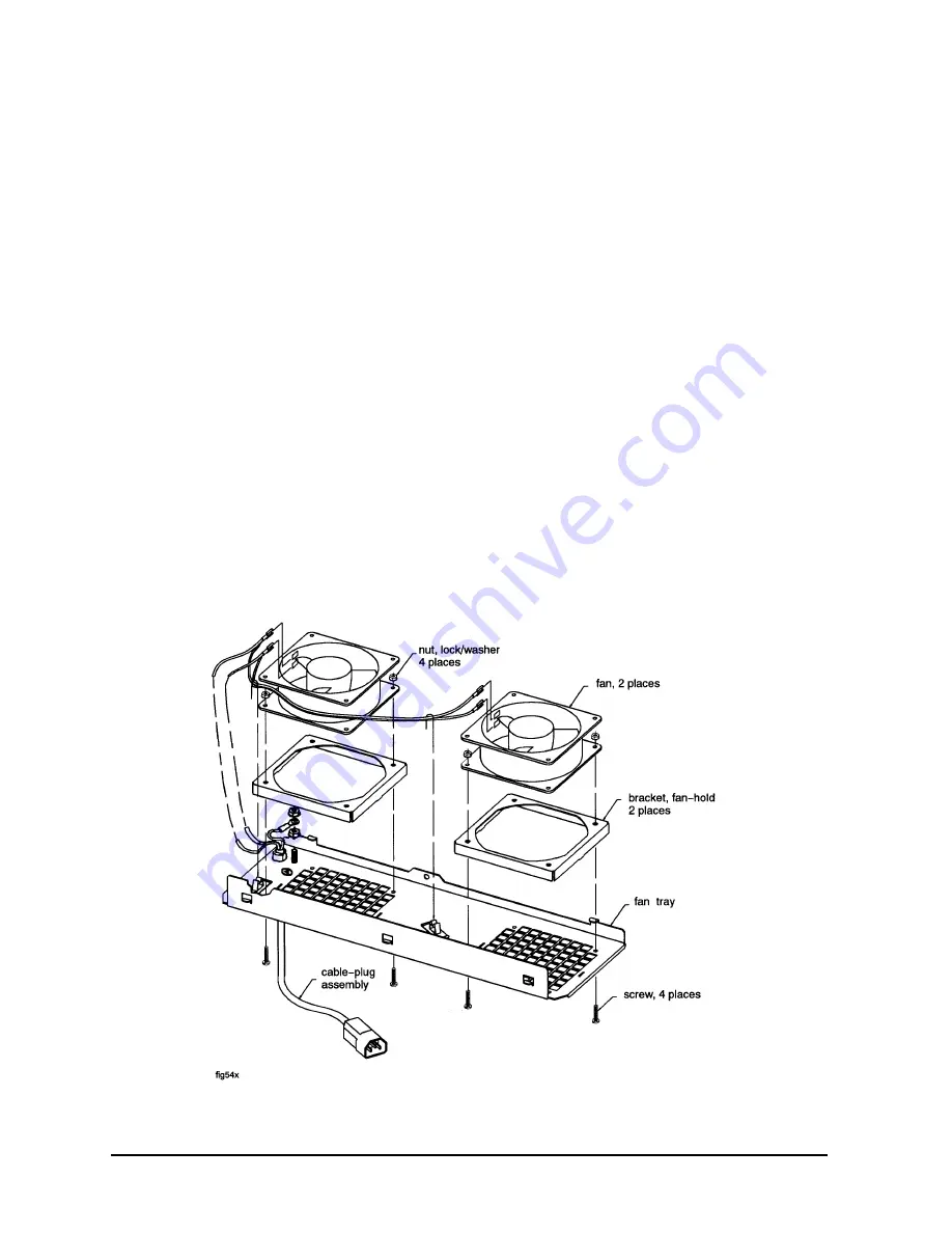
Refer to Figure 5-4 while performing these procedures.
Fan Removal:
1. Remove the fan assembly (refer to fan assembly removal).
2. Remove the power cable connectors from the fan.
3. Remove the two mounting screws and nuts holding the fan to the fan tray.
4. The fan bracket stays with the fan tray.
Fan Replacement:
1. Position the fan over the fan bracket/tray mounting holes so that the power lugs are at
the rear of the fan tray, and on the right side of the fan (as viewed from the back of the
assembly). Also verify the air flow arrow points up.
2. Insert the mounting screws up through the bottom of the fan tray/bracket and fan.
3. Attach mounting nuts/washers on the mounting screw. Tighten screws and nuts.
4. Attach power cord lugs to spades on the fan (polarity does not matter).
5. Replace fan assembly (refer to fan assembly replacement).
Figure 5-4 Fan Diagram
Содержание A1896A
Страница 10: ...1 4 Chapter1 Introduction Required Tools ...
Страница 24: ...4 4 Chapter4 Cabinet Operation Turning Off the Computer System With UPS ...
Страница 26: ...5 2 Chapter5 Removal and Replacement Procedures Figure 5 2 Cabinet Exploded View Rear ...
Страница 36: ...5 12 Chapter5 Removal and Replacement Procedures Removal and Replacement Procedures ...
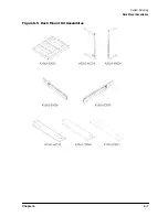
Страница 43: ...Chapter 6 6 7 System Servicing Rack Mount Assemblies Figure 6 5 Rack Mount Kit Assemblies ...
Страница 44: ...6 8 Chapter6 System Servicing Rack Mount Assemblies ...

