h.
Display assembly (see
Display assembly on page 59
)
i.
Top Cover (see
Top cover on page 65
)
j.
Heat sink and fan (see
Heat sink and fan on page 74
)
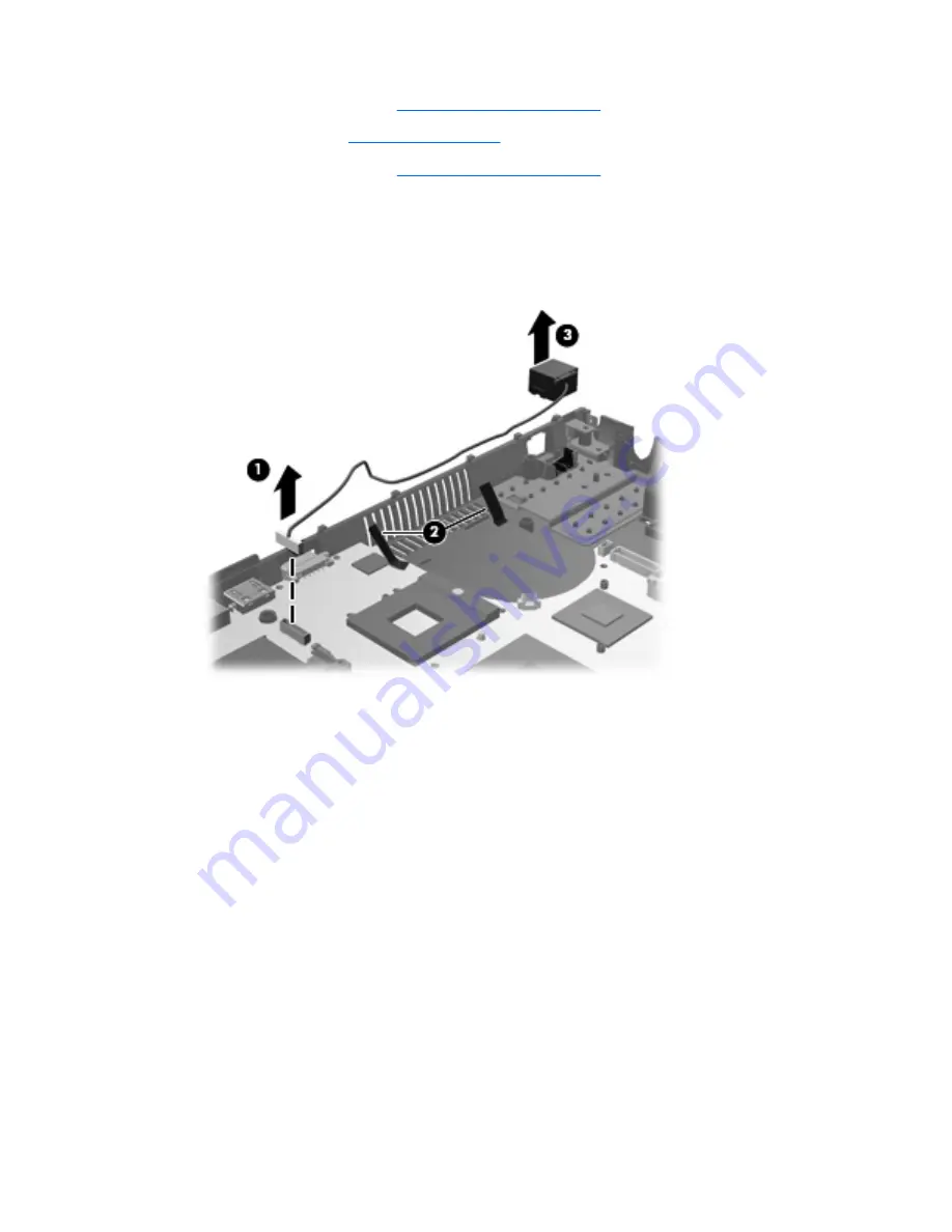
Remove the RJ-45 (network) jack:
1.
Disconnect the RJ-45 (network) cable from the system board
(1)
and remove the tape
(2)
that
secures the cable to the base enclosure.
2.
Lift the RJ-45 (network) jack
(3)
straight up from the retention clips to remove it.
Reverse this procedure to install the RJ-45 (network) jack.
Component replacement procedures
77
Содержание 4710s - ProBook - Core 2 Duo 2.53 GHz
Страница 1: ...HP ProBook 4710s Notebook PC Maintenance and Service Guide ...
Страница 4: ...iv MSG revision history ...
Страница 6: ...vi Safety warning notice ...
Страница 115: ...Where used 3 screws that secure the system board to the base enclosure Phillips PM2 0 3 0 screw 105 ...
Страница 123: ...Where used 1 screw that secures the USB board to the computer Phillips PM2 5 3 0 screw 113 ...
Страница 132: ...Where used 3 screws that secure the system board to the base enclosure 122 Chapter 7 Screw listing ...
Страница 142: ...RJ 11 modem Pin Signal 1 Unused 2 Tip 3 Ring 4 Unused 5 Unused 6 Unused 132 Chapter 9 Connector pin assignments ...
Страница 151: ...22 Remove the LCD panel 23 Recycle the LCD panel and backlight Display 141 ...
Страница 157: ......


