background image

7.

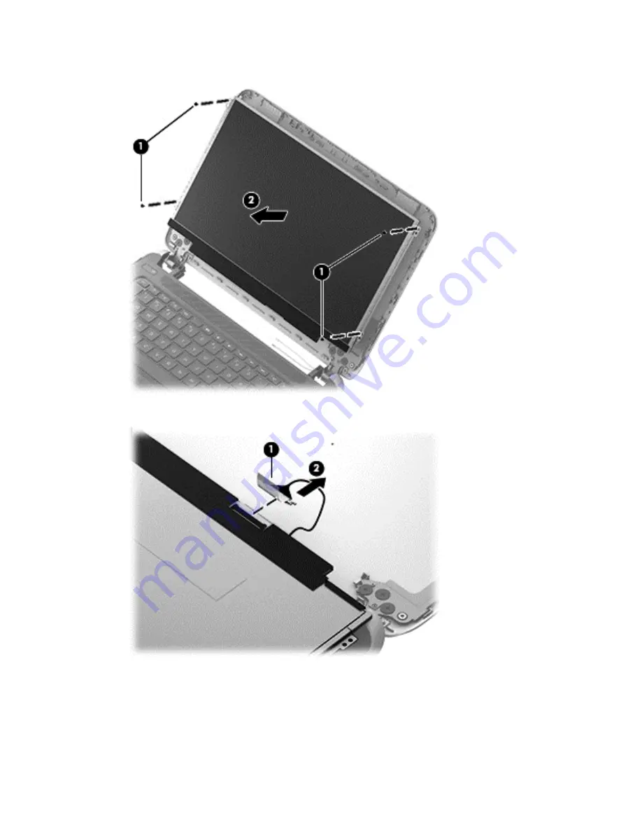
Remove the four Phillips screws 

(1)

 and carefully move the display panel 

(2)

 to the keyboard.

8.

Release the adhesive tape 

(1)

 and disconnect the display panel cable connector 

(2)

.

9.

Remove the display panel.

Reverse this procedure to replace the display panel.

52

Chapter 6   Removal and replacement procedures for Authorized Service Provider parts

Содержание 210 G1

Страница 1: ...HP 210 G1 Notebook PC HP Pavilion 11 Notebook PC HP Pavilion TouchSmart 11 Notebook PC HP 215 G1 Notebook PC Maintenance and Service Guide ...

Страница 2: ...Nothing herein should be construed as constituting an additional warranty HP shall not be liable for technical or editorial errors or omissions contained herein Product notice This guide describes features that are common to most models Some features may not be available on your computer Not all features are available in all editions of Windows 8 This computer may require upgraded and or separatel...

Страница 3: ...hat should only be accessed by an authorized service provider See Chapter 5 Removal and replacement procedures for Customer Self Repair parts for details Accessing parts described in Chapter 6 Removal and replacement procedures for Authorized Service Provider only parts can damage the computer or void your warranty iii ...

Страница 4: ...iv Important Notice about Customer Self Repair Parts ...

Страница 5: ...ow another hard surface such as an adjoining optional printer or a soft surface such as pillows or rugs or clothing to block airflow Also do not allow the AC adapter to contact the skin or a soft surface such as pillows or rugs or clothing during operation The device and the AC adapter comply with the user accessible surface temperature limits defined by the International Standard for Safety of In...

Страница 6: ...vi Safety warning notice ...

Страница 7: ...24 Miscellaneous parts 25 Sequential part number listing 26 4 Removal and replacement procedures preliminary requirements 34 Tools required 34 Service considerations 34 Plastic parts 34 Cables and connectors 35 Drive handling 35 Grounding guidelines 36 Electrostatic discharge damage 36 Packaging and transporting guidelines 37 Workstation guidelines 37 5 Removal and replacement procedures for Custo...

Страница 8: ...d HP PC Hardware Diagnostics UEFI 77 Starting Setup Utility BIOS 77 Updating the BIOS 77 Determining the BIOS version 77 Downloading a BIOS update 78 Downloading a Windows 8 1 BIOS update 78 Downloading a Windows 7 BIOS update 79 Using HP PC Hardware Diagnostics UEFI select models only 79 Downloading HP PC Hardware Diagnostics UEFI to a USB device 80 8 Specifications 81 Computer specifications 81 ...

Страница 9: ... to know 86 Recovering using HP Recovery partition select models only 87 Recovering using the recovery media 87 Changing the computer boot order 88 10 Windows 8 1 Backing up restoring and recovering 89 Creating recovery media and backups 89 Creating HP Recovery media 89 Restore and recovery 90 Recovering using HP Recovery Manager 91 What you need to know 91 Using the HP Recovery partition 91 Using...

Страница 10: ...x ...

Страница 11: ...ache 15 W AMD A6 1450 1 4 GHz turbo 1 0 GHz processor 2 0 MB L2 cache DDR3L 1066 MHz quad core 8 W with dynamic configurable TDP 15 W AMD A4 1250 1 0 GHz processor 1 0 MB L2 cache DDR3L 1333 MHz dual core 8 W Chipset Intel system integrated in CPU AMD system on chip SoC fusion controller hub FCH integrated in accelerated processing unit APU Graphics Internal graphics Support for DX11 HD decode and...

Страница 12: ...computer models with Windows 7 and Windows 8 1 Memory One customer accessible upgradable memory module slot Supports 1333 MHz at 1 35 V single channel DDR3L 1600 MHz downgrade to 1333 MHz for use with A4 1250 processors 1066 MHz at 1 35 V single channel DDR3L 1600 MHz downgrade to 1066 MHz for use with A6 1450 processors Up to 8192 MB of system RAM in the following configurations 8192 MB 1 4096 MB...

Страница 13: ...N options by way of wireless module Two WLAN antennas built into display assembly Support for the following WLAN formats Intel 802 11 a b g n AC 1x1 Bluetooth Combo Adapter Intel 802 11 a b g n AC 2x2 Bluetooth Combo 7260 Adapter select models only Broadcom BCM943228HMB 802 11 a b g n 2x2 WiFi Bluetooth 4 0 Combo Adapter Qualcomm Atheros AR9485 802 11 b g n 1x1 WiFi Adapter select models only Rali...

Страница 14: ...rrect output to wide aspect versus standard aspect video Keyboard pointing devices 91 size textured island style keyboard no numerical keypad Touchpad requirements 2013 Touchpad Taps enabled as default PS 2 interface support Multi Gestures with ability to turn on and off 2 finger scroll Pinch zoom Edge swipe Support for Windows 8 1 Modern TouchPad Gestures not supported on Windows 7 Power requirem...

Страница 15: ...dows 8 1 Small Screen Touch Windows 7 Home Premium for non touchscreen models only Windows 7 Professional 64 for non touchscreen models only Windows 7 Professional 64 with Windows 8 1 Professional 64 product activation key for non touchscreen models only FreeDOS 2 0 for non touchscreen models only Operating system Web supported operating system Windows 8 1 Chinese Markets 64 Windows 8 1 Emerging M...

Страница 16: ...ed separately high speed Internet service purchased from an Internet service provider and a wireless router purchased separately 3 Webcam light On The webcam is in use 4 Webcam Records video captures still photographs and provides access to video conferences and online chat by means of streaming video 5 Internal microphone Records sound The antennas are not visible from the outside of the computer...

Страница 17: ...the button briefly to exit Sleep When the computer is in Hibernation press the button briefly to exit Hibernation CAUTION Pressing and holding down the power button will result in the loss of unsaved information If the computer has stopped responding and Microsoft Windows shutdown procedures are ineffective press and hold the power button down for at least 5 seconds to turn off the computer 2 Spea...

Страница 18: ...ons when pressed in combination with the esc key 3 Windows key Windows 8 Returns you to the Start screen from an open app or the Windows desktop NOTE Pressing the Windows key again will return you to the previous screen Windows 7 Displays the Windows Start menu 4 Action keys Execute frequently used system functions 8 Chapter 2 External component identification ...

Страница 19: ...or in Hibernation Hibernation is a power saving state that uses the least amount of power 2 Caps lock light On Caps lock is on which switches the keys to all capital letters 3 Mute light Amber Computer sound is off Off Computer sound is on 4 Wireless light On An integrated wireless device such as a WLAN device and or a Bluetooth device is on NOTE On some models the wireless light is amber when all...

Страница 20: ...ects or activates items on the screen NOTE The TouchPad also supports edge swipe gestures 2 Left TouchPad button Functions like the left button on an external mouse 3 Right TouchPad button Functions like the right button on an external mouse 10 Chapter 2 External component identification ...

Страница 21: ...is normal for the internal fan to cycle on and off during routine operation 4 USB 2 0 port Connects an optional USB device 5 Memory card reader Reads data from and writes data to memory cards such as Secure Digital SD memory cards 6 Hard drive light Blinking white The hard drive is being accessed Amber HP 3D DriveGuard has temporarily parked the hard drive 7 Power light On The computer is on Blink...

Страница 22: ...evice is connected to the jack the computer speakers are disabled NOTE Be sure that the device cable has a 4 conductor connector that supports both audio out headphone and audio in microphone 2 USB 3 0 port Connect optional USB devices 3 HDMI port Connects an optional video or audio device such as a high definition television any compatible digital or audio component or a high speed HDMI device 4 ...

Страница 23: ...functionality and then contact support through Help and Support 2 Battery lock latch Locks the battery into the battery bay 3 Battery bay Holds the battery 4 Battery release latch Releases the battery from the battery bay Labels The labels affixed to the computer provide information you may need when you troubleshoot system problems or travel internationally with the computer IMPORTANT All labels ...

Страница 24: ...ches the service label on your computer Component 1 Product name 2 Serial number 3 Product number 4 Warranty period 5 Model number select models only Component 1 Serial number 2 Product number 3 Warranty period 4 Model number select models only 5 Revision number Regulatory label s Provide s regulatory information about the computer Wireless certification label s Provide s information about optiona...

Страница 25: ...TE HP continually improves and changes product parts For complete and current information on supported parts for your computer go to http partsurfer hp com select your country or region and then follow the on screen instructions Computer major components 15 ...

Страница 26: ...16 Chapter 3 Illustrated parts catalog ...

Страница 27: ...ormation see Display assembly subcomponents on page 22 2 Keyboard top cover includes keyboard cable and TouchPad For use in Belgium 730895 A41 For use in Bulgaria 730895 BA1 For use in Canada 730895 DB1 For use in the Czech Republic and Slovakia 730895 FL1 For use in Denmark Finland and Norway 730895 DH1 For use in France 730895 051 For use in Germany 730895 041 For use in Israel 730895 BB1 For us...

Страница 28: ...hermal material Equipped with an Intel i3 4010 processors a graphics subsystem with UMA memory for use on computers with Windows 7 or FreeDOS 2 0 operating system 760271 001 Equipped with an Intel i3 4010 processors a graphics subsystem with UMA memory for use on computers with Windows 8 1 Standard 760271 501 Equipped with an Intel i3 4010 processors a graphics subsystem with UMA memory for use on...

Страница 29: ...mory for use on computers with Windows 8 1 Standard operating system 744185 501 Equipped with an AMD A4 1250 processor a graphics subsystem with UMA memory for use on computers with Windows 8 1 Professional operating system 744185 601 Equipped with an AMD A6 1450 processor a graphics subsystem with UMA memory for use on computers with Windows 8 1 Standard operating system 744790 501 Equipped with ...

Страница 30: ...ter models 730887 001 Non touchscreen computer models 747750 001 12 Memory module PC3L 12800 1600 MHz 8 GB 693374 001 4 GB 691740 001 2 GB for use on computer models equipped with an Intel processor 691739 001 13 Rear corner covers 2 included with the bottom cover 14 WLAN module Atheros AR9485 802 11 b g n 1x1 WiFi Adapter 675794 001 Broadcom BCM943228HMB 802 11 a b g n 2x2 WiFi Bluetooth 4 0 Comb...

Страница 31: ...0 GB 5400 rpm 7 0 mm 683802 001 320 GB 5400 rpm 7 0 mm 645193 001 Hard Drive Hardware Kit not illustrated includes hard drive bracket hard drive connector cable and screws 731424 001 18 Li ion battery 3 cell 36 Whr 3 20 Ah 729892 001 6 cell 66 Whr 3 0 Ah 760604 001 19 Service door For use on computer models with an Intel processor 760272 001 For use on computer models with an AMD processor 737253 ...

Страница 32: ...oks HP Pavilion 11 Notebooks touchscreen and HP 215 G1 Notebook PC touchscreen computer models are spared at the display assembly only Item Component Spare part number HP 210 G1 Notebook PC non touchscreen HP Pavilion 11 Notebook PC non touchscreen HP 215 G1 Notebook PC non touchscreen 1 Display bezel 761243 001 756117 001 744179 001 2 Display panel cable includes webcam microphone module cable 74...

Страница 33: ...chscreen 4 Antenna Kit includes left and right wireless antenna cables and transceivers 744177 001 5 11 6 inch 29 46 cm flat display panel HD WLED AG 1366 x 768 3 6 mm standard viewing angle non touchscreen 744182 001 6 Display Hinge Kit includes left and right hinges 744181 001 7 Display back cover 744178 001 Display assembly subcomponents 23 ...

Страница 34: ...d drive does not include hard drive bracket hard drive connector cable or screws 500 GB 5400 rpm 7 0 mm 683802 001 320 GB 5400 rpm 7 0 mm 645193 001 Hard Drive Hardware Kit includes 731424 001 2a Hard drive bracket 2b Hard drive connector cable Screws not illustrated 3 External DVD RW Double Layer with SuperMulti Drive 659940 001 24 Chapter 3 Illustrated parts catalog ...

Страница 35: ...ord 3 pin black 1 83 m For use in Argentina 490371 D01 For use in Denmark 490371 081 For use in Europe 490371 021 For use in Israel 490371 BB1 For use in Italy 490371 061 For use in Japan 490371 291 For use in North America 490371 001 For use in South Korea 490371 AD1 For use in Switzerland 490371 111 For use in Taiwan 490371 AB1 For use in Thailand 490371 201 For use in the United Kingdom and Sin...

Страница 36: ...1 Power cord for use in Thailand 3 pin black 1 83 m 490371 291 Power cord for use in Japan 3 pin black 1 83 m 490371 AB1 Power cord for use in Taiwan 3 pin black 1 83 m 490371 AD1 Power cord for use in South Korea 3 pin black 1 83 m 490371 BB1 Power cord for use in Israel 3 pin black 1 83 m 490371 D01 Power cord for use in Argentina 3 pin black 1 83 m 645193 001 320 GB 5400 rpm SATA 7 0 mm hard dr...

Страница 37: ...600 MHz 693374 001 8 GB memory module PC3L 12800 1600 MHz 709848 001 Realtek RTL8188EE 802 11 b g n 1 1 WiFi Adapter 710662 001 Intel 802 11 a b g n AC 1x1 Bluetooth Combo Adapter 710412 001 65 W HP Smart AC adapter non PFC 4 5 mm 714657 001 65 W HP Smart AC adapter non PFC select models only 4 5 mm 717381 001 Intel 802 11 a b g n AC 2x2 Bluetooth Combo Adapter select models only 729892 001 3 cell...

Страница 38: ... Keyboard top cover for use in Germany includes keyboard cable and TouchPad 730895 051 Keyboard top cover for use in France includes keyboard cable and TouchPad 730895 071 Keyboard top cover for use in Spain includes keyboard cable and TouchPad 730895 131 Keyboard top cover for use in Portugal includes keyboard cable and TouchPad 730895 141 Keyboard top cover for use in Turkey includes keyboard ca...

Страница 39: ...ncludes keyboard cable and TouchPad 730895 BG1 Keyboard top cover for use in Switzerland includes keyboard cable and TouchPad 730895 DB1 Keyboard top cover for use in Canada includes keyboard cable and TouchPad 730895 DH1 Keyboard top cover for use in Denmark Finland and Norway includes keyboard cable and TouchPad 730895 FL1 Keyboard top cover for use in the Czech Republic and Slovakia includes ke...

Страница 40: ...des webcam microphone module cable for non touchscreen computer models 744181 001 Display Hinge Kit includes left and right hinges and 2 rubber screws for non touchscreen computer models 744182 001 11 6 inch 29 46 cm flat display panel HD WLED AG 1366 x 768 3 6 mm standard viewing angle non touchscreen 744183 001 Screw kit 744184 001 Screw pad and display screws for non touchscreen computer models...

Страница 41: ...thermal material 744189 601 System board equipped with an AMD A6 1450 processor a graphics subsystem with UMA memory for use on computers with Windows 8 1 Professional operating system includes replacement thermal material 744192 001 Keyboard top cover for use in the United States includes keyboard cable and TouchPad 744192 161 Keyboard top cover for use in Latin America includes keyboard cable an...

Страница 42: ...ssembly includes webcam microphone module and wireless antenna cables 754263 001 Webcam microphone module non touchscreen computer models 755303 001 11 6 inch 29 46 cm SVA LED touchscreen display assembly includes webcam microphone module and wireless antenna cables 756117 001 Display bezel for non touchscreen computer models 760271 001 System board equipped with an Intel i3 4010 processor a graph...

Страница 43: ...i5 4200U a graphics subsystem with UMA memory for use on computers with Windows 7 or FreeDOS 2 0 operating system 764204 501 System board equipped with an Intel Core i5 4200U a graphics subsystem with UMA memory for use on computers with Windows 8 1 Standard operating system 764204 601 System board equipped with an Intel Core i5 4200U a graphics subsystem with UMA memory for use on computers with ...

Страница 44: ...rations that you must keep in mind during disassembly and assembly procedures NOTE As you remove each subassembly from the computer place the subassembly and all accompanying screws away from the work area to prevent damage Plastic parts CAUTION Using excessive force during disassembly and reassembly can damage plastic parts Use care when handling the plastic parts Apply pressure only at the point...

Страница 45: ...or inserting a hard drive shut down the computer If you are unsure whether the computer is off or in Hibernation turn the computer on and then shut it down through the operating system Before handling a drive be sure that you are discharged of static electricity While handling a drive avoid touching the connector Before removing a diskette drive or optical drive be sure that a diskette or disc is ...

Страница 46: ... components in their electrostatic safe containers until you are ready to install them Before touching an electronic component discharge static electricity by using the guidelines described in this section Avoid touching pins leads and circuitry Handle electronic components as little as possible If you remove a component place it in an electrostatic safe container The following table shows how hum...

Страница 47: ... to ground and that proper materials are selected to avoid static charging When grounding is not possible use an ionizer to dissipate electric charges Workstation guidelines Follow these grounding workstation guidelines Cover the workstation with approved static shielding material Use a wrist strap connected to a properly grounded work surface and use properly grounded tools and equipment Use cond...

Страница 48: ...operator and ground To be effective the conductive must be worn in contact with the skin The following grounding equipment is recommended to prevent electrostatic damage Antistatic tape Antistatic smocks aprons and sleeve protectors Conductive bins and other assembly or soldering aids Nonconductive foam Conductive tabletop workstations with ground cords of one megohm resistance Static dissipative ...

Страница 49: ...n and then follow the on screen instructions Component replacement procedures NOTE Please read and follow the procedures described here to access and replace Customer Self Repair parts successfully NOTE Details about your computer including model serial number product key and length of warranty are on the service tag at the bottom of your computer See Labels on page 13 for details This chapter pro...

Страница 50: ...es use only the user replaceable battery provided with the computer a replacement battery provided by HP or a compatible battery purchased from HP CAUTION Removing a user replaceable battery that is the sole power source for the computer can cause loss of information To prevent loss of information save your work or shut down the computer through Windows before removing the battery 1 Turn the compu...

Страница 51: ...bernation turn the computer on and then shut it down through the operating system 2 Disconnect the power from the computer by unplugging the power cord from the computer 3 Disconnect all external devices from the computer 4 Remove the battery see Battery on page 40 Remove the service door 1 Lift up on the rear edge of the service door 1 until the left and right sides detach from the computer 2 Rem...

Страница 52: ...r If you are unsure whether the computer is off or in Hibernation turn the computer on and then shut it down through the operating system 2 Disconnect the power from the computer by unplugging the power cord from the computer 3 Disconnect all external devices from the computer 4 Remove the battery see Battery on page 40 5 Remove the service door see Service door on page 41 Remove the hard drive 1 ...

Страница 53: ...able 1 from the hard drive c Remove the four Phillips PM3 0 3 25 screws 2 that secure the hard drive bracket to the hard drive d Remove the hard drive bracket 3 from the hard drive The hard drive bracket hard drive connector cable and screws are available in the Hard Drive Hardware Kit spare part number 731424 001 Reverse this procedure to install the hard drive Component replacement procedures 43...

Страница 54: ...ou replace the module and then receive a warning message remove the module to restore device functionality and then contact technical support Before removing the WLAN module follow these steps 1 Turn off the computer If you are unsure whether the computer is off or in Hibernation turn the computer on and then shut it down through the operating system 2 Disconnect the power from the computer by unp...

Страница 55: ...e NOTE If the WLAN antenna cables are not connected to the terminals on the WLAN module the protective sleeves must be installed on the antenna connectors as shown in the following illustration Reverse this procedure to install the WLAN module Component replacement procedures 45 ...

Страница 56: ...y module follow these steps 1 Turn off the computer If you are unsure whether the computer is off or in Hibernation turn the computer on and then shut it down through the operating system 2 Disconnect the power from the computer by unplugging the power cord from the computer 3 Disconnect all external devices from the computer 4 Remove the battery see Battery on page 40 5 Remove the service door se...

Страница 57: ... and or loosened when servicing the computer Make special note of each screw size and location during removal and replacement RTC battery Description Spare part number RTC battery includes double sided tape 738824 001 Before removing the RTC battery follow these steps 1 Turn off the computer If you are unsure whether the computer is off or in Hibernation turn the computer on and then shut it down ...

Страница 58: ...ttom cover The RTC battery is attached to the bottom cover by double sided tape 4 Remove the RTC battery Reverse this procedure to install the RTC battery 48 Chapter 6 Removal and replacement procedures for Authorized Service Provider parts ...

Страница 59: ... 56 Description Spare part number Display bezel HP 210 G1 PC non touchscreen computer models 761243 001 HP 215 G1 PC non touchscreen computer models 744179 001 HP Pavilion 11 Notebook PC non touchscreen computer models 756117 001 Display panel 11 6 inch 29 46 cm flat display panel HD WLED AG 1366 x 768 3 6 mm Standard Viewing Angle non touchscreen 744182 001 IMPORTANT Make special note of each scr...

Страница 60: ...embly 2 Flex the inside edges of the left and right sides 1 and the top edge 2 of the display bezel until the top and sides of the bezel disengage from the display enclosure 3 Partially close the display cover and position the computer with the hinges up 50 Chapter 6 Removal and replacement procedures for Authorized Service Provider parts ...

Страница 61: ...sengage the hinge caps 1 and then use the tool to release the tabs 2 at the bottom of the display bezel 5 Open the display cover and position the computer facing you 6 Remove the display bezel Component replacement procedures 51 ...

Страница 62: ...panel 2 to the keyboard 8 Release the adhesive tape 1 and disconnect the display panel cable connector 2 9 Remove the display panel Reverse this procedure to replace the display panel 52 Chapter 6 Removal and replacement procedures for Authorized Service Provider parts ...

Страница 63: ...inch 29 46 cm SVA LED touchscreen display assembly includes webcam microphone module and wireless antenna cables for use with HP Pavilion TouchSmart 11 Notebook HP Pavilion 11 Notebook touchscreen or HP 215 G1 Notebook PC touchscreen computer models 753948 001 Before removing the display assembly follow these steps 1 Turn off the computer If you are unsure whether the computer is off or in Hiberna...

Страница 64: ... part number 747750 001 for non touchscreen computer models 4 Disconnect the wireless antenna cables 1 from the WLAN module 5 Release the wireless antenna cables from the retention clips 2 and routing channel built into the bottom cover 6 Disconnect the display panel cable 3 from the system board 54 Chapter 6 Removal and replacement procedures for Authorized Service Provider parts ...

Страница 65: ...e four Phillips PM2 0 5 5 screws 1 and the two Phillips PM2 5 10 5 screws 2 that secure the display assembly to the computer 9 Open the display hinges 3 as far as they will open 10 Separate the display assembly 4 from the computer Reverse this procedure to install the display assembly Component replacement procedures 55 ...

Страница 66: ...15 G1 Notebook PC non touchscreen computer models 754263 001 Before removing the display assembly subcomponents follow these steps 1 Turn off the computer If you are unsure whether the computer is off or in Hibernation turn the computer on and then shut it down through the operating system 2 Disconnect the power from the computer by unplugging the power cord from the computer 3 Disconnect all exte...

Страница 67: ...le cable is part of the display panel cable 2 If it is necessary to replace the hinges a Remove the six bottom screws 1 from the display hinges b Remove the hinges 2 from the display enclosure 3 If it is necessary to replace the display panel cable a Release the microphone 1 Component replacement procedures 57 ...

Страница 68: ...m the display back cover The wireless antenna transceivers are attached to the display back cover with double sided tape b Release the wireless antenna cables from the clips 2 built into the display back cover c Remove the wireless antenna cables and transceivers 3 Reverse this procedure to install the display assembly subcomponents 58 Chapter 6 Removal and replacement procedures for Authorized Se...

Страница 69: ...mputer 3 Disconnect all external devices from the computer 4 Remove the battery see Battery on page 40 5 Remove the service door see Service door on page 41 Remove the power connector cable 1 Remove the two Phillips PM2 0 5 5 screws 1 and the Phillips PM2 5 10 5 screw 2 that secure the display assembly right hinge to the computer 2 Open the display assembly right hinge 3 as far as it will open 3 D...

Страница 70: ... from the clips and mold built into the bottom cover 6 Remove the power connector cable Reverse this procedure to install the power connector cable 60 Chapter 6 Removal and replacement procedures for Authorized Service Provider parts ...

Страница 71: ...e battery see Battery on page 40 5 Remove the service door see Service door on page 41 6 Disconnect the RTC battery cable from the system board see RTC battery on page 47 7 Remove the display assembly see Display assembly on page 53 NOTE When replacing the bottom cover be sure that the RTC battery is removed from the defective bottom cover and installed in the replacement bottom cover Remove the b...

Страница 72: ...ble is attached and then disconnect the power button board ribbon cable from the system board 4 Remove the thirteen Phillips PM2 0 4 5 screws that secure the bottom cover to the top cover 62 Chapter 6 Removal and replacement procedures for Authorized Service Provider parts ...

Страница 73: ...the computer by unplugging the power cord from the computer 3 Disconnect all external devices from the computer 4 Remove the battery see Battery on page 40 and then remove the following components a Service door see Service door on page 41 b Display assembly see Display assembly on page 53 c Bottom cover see Bottom cover on page 61 Remove the power button board 1 Remove the two Phillips PM2 0 2 75...

Страница 74: ...3 Remove the power button board 3 and cable Reverse this procedure to install the power button board 64 Chapter 6 Removal and replacement procedures for Authorized Service Provider parts ...

Страница 75: ...r cord from the computer 3 Disconnect all external devices from the computer 4 Remove the battery see Battery on page 40 and then remove the following components a Service door see Service door on page 41 b Display assembly see Display assembly on page 53 c Bottom cover see Bottom cover on page 61 Remove the TouchPad button board 1 Release the ZIF connector 1 to which the TouchPad board cable is a...

Страница 76: ...4 Remove the TouchPad button board 4 and cables Reverse this procedure to install the TouchPad button board 66 Chapter 6 Removal and replacement procedures for Authorized Service Provider parts ...

Страница 77: ...er 4 Remove the battery see Battery on page 40 and then remove the following components a Service door see Service door on page 41 b Display assembly see Display assembly on page 53 c Bottom cover see Bottom cover on page 61 Remove the media card reader board 1 Release the ZIF connector 1 to which the media card reader board cable is attached and then disconnect the media card reader board cable f...

Страница 78: ...from the computer 4 Remove the battery see Battery on page 40 and then remove the following components a Service door see Service door on page 41 b Display assembly see Display assembly on page 53 c Bottom cover see Bottom cover on page 61 Remove the fan 1 Disconnect the fan cable 1 from the system board 2 Detach the cowling tape 2 that secures the fan to the heat sink 3 Remove the two Phillips PM...

Страница 79: ...ct all external devices from the computer 4 Remove the battery see Battery on page 40 and then remove the following components a Service door see Service door on page 41 b Display assembly see Display assembly on page 53 c Bottom cover see Bottom cover on page 61 Remove the monitor connector board 1 Disconnect the monitor connector board cable 1 from the system board 2 Remove the Phillips PM2 0 2 ...

Страница 80: ...pped with an AMD A4 1250 processor a graphics subsystem with UMA memory for use on computers with Windows 7 or FreeDOS 2 0 operating system 730893 001 Equipped with an AMD A6 1450 processor a graphics subsystem with UMA memory for use on computers with the Windows 8 1 Standard operating system 744790 501 Equipped with an AMD A6 1450 processor a graphics subsystem with UMA memory for use on compute...

Страница 81: ...rd drive see Hard drive on page 42 c Display assembly see Display assembly on page 53 d Bottom cover see Bottom cover on page 61 e Media card reader board see Media card reader board on page 67 f Fan see Fan on page 68 NOTE When replacing the system board be sure that the following components are removed from the defective system board and installed on the replacement system board WLAN module see ...

Страница 82: ...system board 4 Remove the three Phillips PM2 0 4 5 screws 1 that secure the system board to the top cover 5 Lift the left side of the system board 2 until it rests at an angle 72 Chapter 6 Removal and replacement procedures for Authorized Service Provider parts ...

Страница 83: ...ter If you are unsure whether the computer is off or in Hibernation turn the computer on and then shut it down through the operating system 2 Disconnect the power from the computer by unplugging the power cord from the computer 3 Disconnect all external devices from the computer 4 Remove the battery see Battery on page 40 and then remove the following components a Service door see Service door on ...

Страница 84: ... the system board 3 Remove the heat sink 2 NOTE Due to the adhesive quality of the thermal material located between the heat sink and the system board components it may be necessary to move the heat sink from side to side to detach it NOTE The thermal material must be thoroughly cleaned from the surfaces of the heat sink and the system board components each time the heat sink is removed Thermal pa...

Страница 85: ...isconnect the power from the computer by unplugging the power cord from the computer 3 Disconnect all external devices from the computer 4 Remove the battery see Battery on page 40 and then remove the following components a Service door see Service door on page 41 b Hard drive see Hard drive on page 42 c Display assembly see Display assembly on page 53 d Bottom cover see Bottom cover on page 61 e ...

Страница 86: ... 75 screws 1 and the two Phillips PM2 0 2 75 screws 2 that secure the speakers to the bottom cover 2 Remove the speakers 3 Reverse this procedure to install the speakers 76 Chapter 6 Removal and replacement procedures for Authorized Service Provider parts ...

Страница 87: ...IOS Updated versions of the BIOS may be available on the HP website Most BIOS updates on the HP website are packaged in compressed files called SoftPaqs Some download packages contain a file named Readme txt which contains information regarding installing and troubleshooting the file Determining the BIOS version To determine whether available BIOS updates contain later BIOS versions than those cur...

Страница 88: ... need this information to locate the update later after it has been downloaded to your hard drive b Follow the on screen instructions to download your selection to the hard drive If the update is more recent than your BIOS make a note of the path to the location on your hard drive where the BIOS update is downloaded You will need to access this path when you are ready to install the update NOTE If...

Страница 89: ...S installation procedures vary Follow any instructions that are displayed on the screen after the download is complete If no instructions are displayed follow these steps 1 Open Windows Explorer by selecting Start Computer 2 Double click your hard drive designation The hard drive designation is typically Local Disk C 3 Using the hard drive path you recorded earlier open the folder on your hard dri...

Страница 90: ... to run and then follow the on screen instructions NOTE If you need to stop a diagnostic test press esc Downloading HP PC Hardware Diagnostics UEFI to a USB device NOTE The HP PC Hardware Diagnostics UEFI download instructions are provided in English only 1 Go to http www hp com 2 Click Support Drivers and then click the Drivers Software tab 3 Enter the product name in the text box and then click ...

Страница 91: ...ter models 1 53 kg 3 37 lbs HP Pavilion 11 Notebook PC non touchscreen computer models 1 50 kg 3 31 lbs Input power Operating voltage and current 19 5 V dc 2 31 A 45 W 19 5 V dc 3 33 A 65 W Temperature Operating 5 C to 35 C 41 F to 95 F Nonoperating 20 C to 60 C 4 F to 140 F Relative humidity noncondensing Operating 10 to 90 Nonoperating 5 to 95 Maximum altitude unpressurized Operating 15 m to 3 0...

Страница 92: ... typical read including setting Single track 1 5 ms 1 5 ms Average read write 11 13 ms 11 13 ms Maximum 22 ms 22 ms Logical blocks 976 773 168 628 142 448 Disk rotational speed 5400 rpm 5400 rpm Operating temperature 0 C to 60 C 32 F to 140 F 0 C to 60 C 32 F to 140 F 1 GB 1 billion bytes when referring to hard drive storage capacity Actual accessible capacity is less NOTE Certain restrictions and...

Страница 93: ...very Manager examines the computer and determines the required storage capacity for the flash drive or the number of blank DVD discs that will be required Use DVD R DVD R DVD R DL DVD R DL discs or a flash drive Do not use rewriteable discs such as CD RW DVD RW double layer DVD RW and BD RE rewritable Blu ray discs they are not compatible with HP Recovery Manager software You can use an optional e...

Страница 94: ...to the state it was on the previous day the software will be uninstalled and you won t be able to use it What you need to know If you restore to a restore point and then change your mind you can undo the restoration You should create system restore points Before you add or change software or hardware Periodically whenever the computer is running normally System Restore also saves shadow copies of ...

Страница 95: ...e amount of free space on your backup storage device before you back up You should back up Before adding or changing software or hardware Before the computer is repaired or restored On a regular schedule to be sure you have recent copies of personal information After you add many files for example if you saved videos from a birthday party Before using antivirus software to remove a malicious progr...

Страница 96: ...t were backed up using Windows Backup and Restore 1 Select Start Control Panel System and Security Backup and Restore 2 Follow the on screen instructions to restore your backup NOTE Windows includes the User Account Control feature to improve the security of the computer You may be prompted for your permission or password for tasks such as installing software running utilities or changing Windows ...

Страница 97: ... discs have been included if your computer did not ship with a recovery partition 1 Access HP Recovery Manager in either of the following ways Select Start and type recovery in the search field Select Recovery Manager from the list or Turn on or restart the computer and then press esc while the Press the ESC key for Startup Menu message is displayed at the bottom of the screen Then press f11 while...

Страница 98: ...ions 3 Select Internal CD DVD ROM Drive from the boot options window To change the boot order for a recovery flash drive 1 Insert the flash drive into a USB port 2 Restart the computer 3 Press esc while the computer is restarting and then press f9 for boot options 4 Select the flash drive from the boot options window 88 Chapter 9 Windows 7 Backing up restoring and recovering ...

Страница 99: ...g recovery options System Recovery Reinstalls the original operating system and the programs that were installed at the factory Minimized Image Recovery Reinstalls the operating system and all hardware related drivers and software but not other software applications Factory Reset Restores the computer to the state its original factory state by deleting all information from the hard drive and re cr...

Страница 100: ...b Be sure that the computer is connected to AC power before you begin creating the recovery media The creation process can take up to an hour or more Do not interrupt the creation process If necessary you can exit the program before you have finished creating all of the recovery DVDs HP Recovery Manager will finish burning the current DVD The next time you start HP Recovery Manager you will be pro...

Страница 101: ...ed drivers and software but not other software applications Factory Reset Restores the computer to the state its original factory state by deleting all information from the hard drive and re creating the partitions Then it reinstalls the operating system and the software that was installed at the factory The HP Recovery partition allows System Recovery and Minimized Image Recovery What you need to...

Страница 102: ...ns Changing the computer boot order If computer does not restart in HP Recovery Manager you can change the computer boot order which is the order of devices listed in BIOS where the computer looks for startup information You can change the selection for an optical drive or a USB flash drive To change the boot order 1 Insert the HP Recovery media you created 2 Restart the computer 3 Press and hold ...

Страница 103: ... to remove the HP Recovery partition 1 From the Start screen type recovery and then select HP Recovery Manager 2 Select Remove Recovery Partition and follow the on screen instructions to continue Restore and recovery 93 ...

Страница 104: ...rements are applicable to all countries and regions The length of the power cord set must be at least 1 0 m 3 3 ft and no more than 2 0 m 6 5 ft All power cord sets must be approved by an acceptable accredited agency responsible for evaluation in the country or region where the power cord set will be used The power cord sets must have a minimum current capacity of 10 A and a nominal voltage rating...

Страница 105: ...ark DEMKO 1 Finland FIMKO 1 France UTE 1 Germany VDE 1 India ISI 1 Israel SII 1 Italy IMQ 1 Japan JIS 3 The Netherlands KEMA 1 New Zealand SANZ 1 Norway NEMKO 1 The People s Republic of China CCC 4 Saudi Arabia SASO 7 Singapore PSB 1 South Africa SABS 1 South Korea KTL 5 Sweden SEMKO 1 Switzerland SEV 1 Taiwan BSMI 6 Thailand TISI 1 The United Kingdom ASTA 1 Requirements for specific countries and...

Страница 106: ...nductor size The wall plug must be a two pole grounding type with a Japanese Industrial Standard C8303 7 A 125 V ac configuration 4 The flexible cord must be Type RVV 3 conductor 0 75 mm conductor size Power cord set fittings appliance coupler and wall plug must bear the CCC certification mark 5 The flexible cord must be Type H05VV F 3 conductor 0 75 mm conductor size KTL logo and individual appro...

Страница 107: ...he battery in general household waste Follow the local laws and regulations in your area for battery disposal HP encourages customers to recycle used electronic hardware HP original print cartridges and rechargeable batteries For more information about recycling programs see the HP Web site at http www hp com recycle 97 ...

Страница 108: ... computer major components 15 specifications 81 connectors service considerations 35 D deleted files restoring for Windows 8 1 computer models 90 restoring in Windows 7 86 display assembly removal 53 spare part number 17 32 53 spare part numbers 56 subcomponents 22 display assembly subcomponents removal 56 display back cover spare part numbers 23 56 display bezel spare part number 22 32 33 49 disp...

Страница 109: ... keys action 8 esc 8 fn 8 operating system 8 Windows 8 L labels Bluetooth 14 regulatory 14 serial number 14 service 13 wireless certification 14 WLAN 14 left side components 11 light components 9 lights AC adapter 12 caps lock 9 hard drive 11 mute 9 power 9 11 webcam 6 wireless 9 M mass storage device illustrated 24 precautions 35 spare part numbers 24 media card reader board removal 67 spare part...

Страница 110: ...y discs Windows 7 83 recovery for Windows 7 86 recovery in Windows 7 HP Recovery Manager 86 recovery media creating for Windows 8 computer models 89 creating using HP Recovery Manager for Windows 8 1 computer models 90 recovery media Windows 7 83 recovery partition for Windows 8 1 computer models 91 removing for Windows 8 1 computer models 92 recovery Windows 7 system 86 regulatory information reg...

Страница 111: ...guidelines 37 traveling with the computer 14 U USB port 11 12 V vents 11 video product description 3 W webcam light 6 webcam location 6 webcam microphone module removal 56 spare part number 22 32 56 Windows File History 90 restoring files 90 Windows 7 Backup and Restore restoring files 86 Windows 8 1 system restore point 89 Windows key 8 wireless antenna removal 58 spare part number 23 56 wireless...

Отзывы: