13
INSTALLATION OF CONTROL
PANEL AND SENSOR
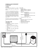
Detailed instructions for the installation
of both the control panel and the sensor
are delivered with the control panel.
INSTALLATION OF HEATER
The heater may only be connected to
the electrical network in accordance with
the current regulations by an authorized,
professional electrician.
The wiring diagrams are included in the
control unit’s installation instruction.
Further instructions concerning
exceptional installations can be obtained
from local electrical authorities.
1. Remove heater from carton and place
in proper location in sauna room.
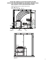
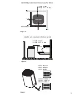
Observe proper clearances as per
figures 2 - 6 and table 1. After final
hookup, electrical contractor should
secure heater to floor with at least two
screws or bolts.
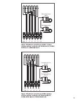
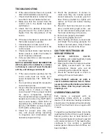
2. See applicable wiring diagram for
heater model (figures 8 - 9, see control
unit manual for detailed instructions
how to connect the heater and
the control unit). Heater must be
permanently installed (no pigtails or
plugs allowed) and wiring must be
done by a licensed electrician, who
must follow wiring diagram provided
and adhere to local codes. Use proper
A.W.G rated wire size and use copper
wire suitable for 194°F (91°C) within
sauna walls. Use grounding terminals
provided in sauna heater and control
unit to properly ground the equipment
as per NEC and local codes.
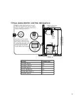
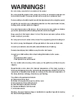
3. Inside the heater box there are
two signs. Please place the metal
“CAUTION” sign on the interior wall
of the sauna room directly above
the heater in a visible place. Place
the metal “WARNING” sign outside,
on the door of the sauna room.
“MAINTENANCE INSTRUCTIONS”
are at the end of this manual.
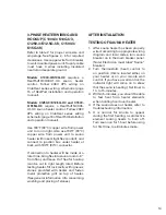
SINGLE PHASE HEATER WIRING
AND HOOKUP (C1000/K10G-U1,
C1250/K12.5G-U1, C1500/
K15G-U1)
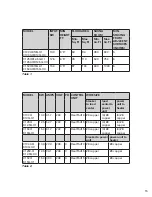
Refer to table 2 for proper wire size and
amperage. See figures 2 - 6 for required
clearances. Use copper wire from breaker
to wall-mounted power unit. Supply cable
must have 5 wires including insulated
neutral and separate ground.
Model C1000/K10G-U1
requires a
HeatPad10/CX30-U1-U3 sauna heater
control. Follow 240V 1Ph (dual circuit)
wiring on ClubHeat series wiring
schematic (page 15 of HeatPad installation
and operation manual).
Models C1250/K12.5G-U1 and C1500/
K15G-U1
require a HeatPad15/CX-45-
U1-U3 sauna heater control, follow 240V
1Ph (dual circuit) wiring on ClubHeat series
wiring schematic (page 15 of HeatPad
installation and operation manual).
Use 194°F (90°C) copper wire from power
unit to room light. Also use 194°F (90°C)
copper wire from power unit to sauna
heater (within seal tight flex conduit), and
connect to junction box under heater at
back, with 194°F (90°C) connector.
Cutler-Hammer model CH4F load center
shall be supplied by electrical contractor.
If connection to heater will be made at a
later time, bring flex into sauna room 4 - 6”
from floor, and leave 3’ of flex for hookup
(can be cut to right length later). Before
testing heater, fill rock cavity with igneous
stones provided with heater and fasten
metal protective grill on top of heater.
(See general information info concerning
washing and placing of stones.)


