13
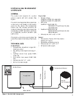
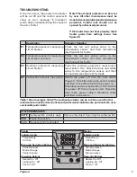
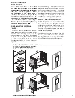
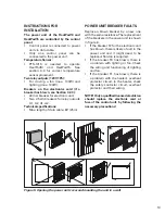
Figure 5. Opening the power unit cover and mounting the unit to a wall
INSTRUCTIONS FOR
INSTALLATION
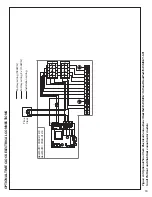
The power unit of the HeatPad10 and
HeatPad15 are controlled by the control
panel.
• Control panel is connected to power
unit via data cable.
• Only one control panel can be
connected to the power unit.
Temperature Sensor:
• PTS-1015 is needed to operate
HeatPad10 and HeatPad15. See
section 3.3 for correct temperature
sensor placement.
Two relay outputs (120V 1Ph):
• For driving a fan (max. 100W) and
lighting (max. 100W).
Breakers on the electronics card (if a
breaker has blown, see Section 3.2.3.):
• 40 mA breaker for electronic unit.
• Two 2.5 Ah breakers for relay outputs
U1, U2, A1, A2.
Technical specifications:
• Max. length of data cable: 80’ (25m)
POWER UNIT BREAKER FAULTS
Replace a blown breaker by a new one
with the same resistance. The replacement
of the breakers in the power unit is shown
in figure 6.
• If the breaker F2 for the electronic unit
has blown, there is likely a fault in the
power unit and it might need to be
replaced. Service is required.
• If the breaker F3 has blown, there is
a problem with lighting or fan. Check
the wiring and functioning of lighting
and fan.
• If the breaker F1 has blown, there is
a problem with the heater’s overheat
protector circuit. In the heater, check
the safety contactor circuit, overheat
protector and their wiring.
NOTE! Only a qualified licensed electrician
should replace the electronic card or
fuse of the control unit, by following the
necessary precautions!

