background image

26

[b] KM-101BAH

Содержание KM-61BAH

Страница 1: ...SERVICE MANUAL HOSHIZAKI SELF CONTAINED CRESCENT CUBER MODEL KM 61BAH KM 101BAH KM 151BAH KM 151BWH NO M006 749 ISSUED FEB 18 2008 REVISED JUN 17 2011 ...

Страница 2: ...and service of the unit Should the reader have any questions or concerns which have not been satisfactorily addressed please call write or send an e mail message to the Hoshizaki Technical Support Department for assistance HOSHIZAKI AMERICA INC 618 Highway 74 South Peachtree City GA 30269 Attn Hoshizaki Technical Support Department Phone 1 800 233 1940 Technical Support 770 487 2331 Fax 1 800 843 ...

Страница 3: ...1BAH 3 d KM 151BWH 4 II GENERAL INFORMATION 5 1 CONSTRUCTION 5 a KM 61BAH KM 101BAH 5 b KM 151BAH 6 c KM 151BWH 7 d ICEMAKING COMPARTMENT 8 2 SEQUENCE OF OPERATION 9 a ONE MINUTE FILL CYCLE 9 b INITIAL HARVEST CYCLE 9 c FREEZE CYCLE 9 d DRAIN CYCLE 10 e NORMAL HARVEST CYCLE 10 3 CONTROL BOARD 12 a CONTROL BOARD LAYOUT 13 b FEATURES 14 c CONTROLS AND ADJUSTMENTS 16 d CONTROL BOARD CHECK PROCEDURE 1...

Страница 4: ...ANT LINES 41 a SERVICE INFORMATION 41 b REFRIGERANT RECOVERY 42 c EVACUATION AND RECHARGE 42 2 BRAZING 43 3 COMPRESSOR 44 4 DRIER 45 5 HOT GAS VALVE 46 6 EXPANSION VALVE KM 151BAH KM 151BWH ONLY 48 7 WATER REGULATING VALVE KM 151BWH ONLY 50 8 ADJUSTMENT OF WATER REGULATING VALVE KM 151BWH ONLY 51 9 WATER COOLED CONDENSER KM 151BWH ONLY 52 10 FAN MOTOR 54 11 PUMP MOTOR 55 12 WATER VALVE 56 13 CLEAN...

Страница 5: ... GUIDE 69 21 SEPARATOR 70 22 SPRAY TUBE WATER SUPPLY PIPE SPRAY GUIDE 70 23 DOOR 71 VI CLEANING AND MAINTENANCE INSTRUCTIONS 72 1 CLEANING 72 a CLEANING PROCEDURE 72 b SANITIZING PROCEDURE 74 2 MAINTENANCE 75 a EXTERIOR PANELS 75 b STORAGE BIN AND SCOOP 75 c AIR FILTER 75 d CONDENSER 75 3 PREPARING THE ICEMAKER FOR LONG STORAGE 76 iii ...

Страница 6: ...C Cord Connection WATER SUPPLY Inlet 1 2 FPT DRAIN Outlet 3 4 FPT CUBE CONTROL SYSTEM Float Switch HARVESTING CONTROL SYSTEM Hot Gas and Water Thermistor and Timer ICE MAKING WATER CONTROL Timer Controlled Overflow Pipe COOLING WATER CONTROL N A BIN CONTROL SYSTEM Mechanical Level Switch with Delay COMPRESSOR Hermetic Model QA51K13GAU6 E0GS CONDENSER Air Cooled Fin and tube type EVAPORATOR Vertica...

Страница 7: ...ion WATER SUPPLY Inlet 1 2 FPT DRAIN Outlet 3 4 FPT CUBE CONTROL SYSTEM Float Switch HARVESTING CONTROL SYSTEM Hot Gas and Water Thermistor and Timer ICE MAKING WATER CONTROL Timer Controlled Overflow Pipe COOLING WATER CONTROL N A BIN CONTROL SYSTEM Mechanical Level Switch with Delay COMPRESSOR Hermetic Model QA91K22CAU6 E0GS CONDENSER Air Cooled Fin and tube type EVAPORATOR Vertical type Stainle...

Страница 8: ... WATER SUPPLY Inlet 1 2 FPT DRAIN Outlet 3 4 FPT CUBE CONTROL SYSTEM Float Switch HARVESTING CONTROL SYSTEM Hot Gas and Water Thermistor and Timer ICE MAKING WATER CONTROL Timer Controlled Overflow Pipe COOLING WATER CONTROL N A BIN CONTROL SYSTEM Mechanical Level Switch with Delay COMPRESSOR Hermetic Model QA125K29CAU6 E0GS CONDENSER Air Cooled Fin and tube type EVAPORATOR Vertical type Stainless...

Страница 9: ...ction WATER SUPPLY Inlet 1 2 FPT DRAIN Outlet 3 4 FPT CONDENSER WATER Inlet 1 2 FPT Outlet 1 2 FPT CUBE CONTROL SYSTEM Float Switch HARVESTING CONTROL SYSTEM Hot Gas and Water Thermistor and Timer ICE MAKING WATER CONTROL Timer Controlled Overflow Pipe COOLING WATER CONTROL N A BIN CONTROL SYSTEM Mechanical Level Switch with Delay COMPRESSOR Hermetic Model QA125K29CAU6 E0GS CONDENSER Water Cooled ...

Страница 10: ...ter Supply Tube Front Panel Tank Louver Control Box Control Switch Condenser Fan Motor Hot Gas Valve Air Filter Front View Thermistor Cleaning Valve Water Valve Rear Panel Pump Motor Power Supply Pipe Cover Cord Drain Valve Drier Compressor Rear View Rear Cover Float Switch With Tank Removed Bin Control Switch ...

Страница 11: ...k Louver Control Box Control Switch Condenser Compressor Hot Gas Valve Air Filter Front View Fan Motor Thermistor Cleaning Valve Water Valve Rear Panel Pump Expansion Valve Motor Power Supply Pipe Cover Cord Drier Drain Valve Rear View Rear Cover Float Switch Bin Control Switch With Tank Removed ...

Страница 12: ...trol Switch Control Box Fan Motor Air Filter Front View Condenser Compressor Cleaning Valve Thermistor Water Valve Pump Motor Expansion Valve Rear Panel Drain Valve Power Hot Gas Valve Supply Pipe Cover Cord Rear Cover Rear View Drier Water Regulating Valve Float Switch Bin Control Switch With Tank Removed ...

Страница 13: ...8 d ICEMAKING COMPARTMENT Water Valve Cleaning Valve Spray Tube Water Supply Pipe Evaporator Pump Motor Separator Cube Guide Float Switch Water Tank ...

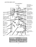
Страница 14: ... the freeze cycle starts The minimum total time allowed by the board for a complete harvest cycle is 2 minutes WV is open during harvest for a maximum of 6 minutes or the length of harvest minus 0 10 30 or 50 seconds adjustable by S1 dip switch 7 8 whichever is shorter LED 8 goes off when WV closes PM energizes and runs for the last 0 10 30 or 50 seconds of harvest depending on S1 dip switch 7 8 s...

Страница 15: ...pen during harvest for a maximum of 6 minutes or the length of harvest minus 0 10 30 or 50 seconds adjustable by S1 dip switch 7 8 whichever is shorter LED 8 goes off when WV closes PM energizes and runs for the last 0 10 30 or 50 seconds of harvest depending on S1 dip switch 7 8 setting LED 7 comes on when PM energizes At the end of harvest the control board checks the position of F S and proceed...

Страница 16: ...11 ...

Страница 17: ...ains integrated circuits which are susceptible to failure due to static discharge It is especially important to touch the metal part of the unit before handling or replacing the board 3 Do not touch the electronic devices on the board or the back of the board to prevent damage to the board 4 Do not change wiring and connections 5 Always replace the whole board assembly when it goes bad 6 Do not sh...

Страница 18: ...service board only Relay LEDs 6 indicate which relays are energized as listed below LED 5 X1 Relay Compressor Comp Remote Fan Motor FMR LED 6 X2 Relay Hot Gas Valve HGV Self Contained Fan Motor FMS FMS off when LED on LED 8 X4 Relay Inlet Water Valve WV Harvest Water Valve HWV on units with two inlet water valves LED 9 X5 Relay Freeze Water Valve FWV on units with two inlet water valves service bo...

Страница 19: ...down the circuit and the icemaker automatically stops The control board will signal this problem using 1 beep every 3 seconds The alarm reset button on the control board must be pressed with power on to reset the safety d Low Water Safety The control board checks the position of the float switch at the end of the initial one minute water fill cycle and at the end of each harvest cycle If the float...

Страница 20: ...PERATION Sequence Step LED Energized Components Time LEDs are On Min Max Avg 1 Minute Fill Cycle 8 WV 60 seconds Harvest Cycle 5 6 8 WV HGV Comp 2 minutes 20 minutes 3 to 5 minutes Last 0 10 30 or 50 seconds adjustable by dip switch of harvest WV de energizes and PM energizes LEDs 5 6 and 7 are on Freeze Cycle 5 7 Comp PM FMS 5 minutes freeze timer setting 30 to 35 minutes Drain 5 6 4 Comp HGV DV ...

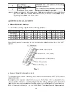
Страница 21: ...OFF ON OFF ON KM 101BAH ON OFF ON ON ON ON OFF ON OFF ON KM 151BWH OFF OFF ON ON ON ON OFF ON ON OFF If the S2 dip switch is mounted on the control board all should be left in the OFF position Fig 1 Freeze Timer 9 10 Water Saver Timer 7 8 Drain Frequency Control 5 6 Drain Timer 3 4 Harvest Timer 1 2 b Harvest Timer S1 dip switch 1 2 The harvest timer starts counting when the thermistor reads 48 F ...

Страница 22: ... T1 T2 OFF OFF 10 120 ON OFF 10 180 OFF ON 20 120 ON ON 20 180 T1 Time to drain the water tank T2 Harvest timer at drain Drain cycle always occurs on the 2nd harvest after startup Then depending on the drain frequency control setting dip switch 5 6 drain cycle occurs every cycle or every 2nd 5th or 10th cycle d Drain Frequency Control S1 dip switch 5 6 The water tank drains at the frequency set by...

Страница 23: ... proper specification or the unit may not operate correctly The freeze timer setting determines the maximum allowed freeze time to prevent possible freeze up issues Upon termination of freeze timer machine initiates the harvest cycle After 2 consecutive timer terminations machine will shut down possibly indicating a problem The freeze timer is factory adjusted and no adjustment is required Dip Swi...

Страница 24: ...in the OFF position 4 HARVEST CONTROL THERMISTOR A thermistor semiconductor is used as a harvest control sensor and anti slush sensor The resistance varies depending on the suction line temperatures The thermistor detects the temperature of the evaporator outlet to start the harvest timer or momentarily stop the pump motor during the freeze cycle No adjustment is required If necessary check for re...

Страница 25: ...es 36 F 2 C If during the freeze cycle ice pushes in the lever after the five minute timer expires the control board will allow the machine to complete the freeze cycle and the following harvest cycle before shutting down the machine b BIN CONTROL CHECK PROCEDURE 1 Clear any ice away from the bin control 2 Make sure the control switch is in the ICE position 3 Check that the POWER OK LED on the con...

Страница 26: ...nto one of three modes OFF center position ICE right position and WASH left position Fig 3 1 OFF In the OFF position no power is supplied to the unit However to avoid any possible risk of electrical shock disconnect the power before servicing 2 ICE This position applies power to the unit causing the automatic icemaking process to begin Refer to 2 SEQUENCE OF OPERATION for further details 3 WASH Wh...

Страница 27: ... TECHNICAL INFORMATION 1 WATER CIRCUIT AND REFRIGERANT CIRCUIT a KM 61BAH KM 101BAH Drain Valve Drain Outlet Hot Gas Valve Accumulator Insulation Drier Capillary Tube Evaporator Fan Condenser Spray Tube Water Valve Water Inlet Float Switch Cleaning Valve Thermistor Insulation ...

Страница 28: ...er Tank Compressor Water Circuit Refrigeration Circuit Drain Valve Drain Outlet Hot Gas Valve Drier Expansion Valve Evaporator Fan Condenser Spray Tube Water Valve Water Inlet Float Switch Cleaning Valve Thermistor Pressure Switch ...

Страница 29: ...ter Circuit Refrigeration Circuit Drain Valve Drain Outlet Hot Gas Valve Expansion Valve Evaporator Condenser Spray Tube Water Valve Water Inlet Float Switch Cleaning Valve Thermistor Pressure Switch Drain Water Regulating Valve Condenser Water Supply ...

Страница 30: ...25 2 WIRING DIAGRAM a KM 61BAH ...

Страница 31: ...26 b KM 101BAH ...

Страница 32: ...27 c KM 151BAH KM 151BWH ...

Страница 33: ...Code V 0 or earlier PART NAME COMPRESSOR ON OFF OFF ON OFF CONTROL BOARD RELAY X6 DV RELAY X1 COMP RELAY X2 HV FM ON RELAY X3 PM OFF RELAY X4 WV ON ON OFF ON OFF ON OFF OFF ON OFF CLEANING VALVE ON OFF FLOAT SWITCH ON OFF BIN CONTROL SWITCH ON OFF DRAIN VALVE HARVEST CYCLE Thermistor senses 9 C after more than 8 min 30 sec in harvest cycle Ver 3 1 or later HOT GAS VALVE WATER VALVE ON OFF FAN MOTO...

Страница 34: ...0 27 11 0 8 13 0 9 17 1 2 90 32 11 0 8 15 1 1 18 1 3 PSIG kg cm2 G 100 38 12 0 9 16 1 1 21 1 5 1 600 BTU h AT 90 F 32 C WT 70 F 21 C Note Pressure data is recorded at 5 minutes into freezing cycle The data not in bold should be used for reference only We reserve the right to make changes in specifications and design without prior notice TOTAL HEAT OF REJECTION FROM CONDENSER 2 0 SUCTION PRESSURE H...

Страница 35: ...14 1 0 17 1 2 20 1 4 90 32 14 1 0 19 1 3 23 1 6 PSIG kg cm2 G 100 38 15 1 0 20 1 4 26 1 8 2 320 BTU h AT 90 F 32 C WT 70 F 21 C Note Pressure data is recorded at 5 minutes into freezing cycle The data not in bold should be used for reference only We reserve the right to make changes in specifications and design without prior notice TOTAL HEAT OF REJECTION FROM CONDENSER 2 0 SUCTION PRESSURE HARVES...

Страница 36: ... 80 27 13 0 9 14 1 0 15 1 1 90 32 13 0 9 15 1 1 16 1 1 PSIG kg cm2 G 100 38 13 0 9 15 1 1 17 1 2 3 840 BTU h AT 90 F 32 C WT 70 F 21 C Note Pressure data is recorded at 5 minutes into freezing cycle The data not in bold should be used for reference only We reserve the right to make changes in specifications and design without prior notice TOTAL HEAT OF REJECTION FROM CONDENSER 2 0 SUCTION PRESSURE...

Страница 37: ...9 14 1 0 80 27 13 0 9 14 1 0 14 1 0 90 32 13 0 9 14 1 0 15 1 0 PSIG kg cm2 G 100 38 13 0 9 14 1 0 15 1 1 3 840 BTU h AT 90 F 32 C WT 70 F 21 C Note Pressure data is recorded at 5 minutes into freezing cycle The data not in bold should be used for reference only We reserve the right to make changes in specifications and design without prior notice TOTAL HEAT OF REJECTION FROM CONDENSER 2 0 SUCTION ...

Страница 38: ...ection during initial start up and at the end of each harvest Diagnosis If the water valve does not open check for no supply voltage at water valve terminals bad coil or plugged screen or external filter no water flow If unit fails to start harvest check for open float switch or bad 1 minute timer in board 4 Initial Harvest Cycle The inlet water valve remains energized contactor coil energizes to ...

Страница 39: ...he float switch removed replace the board Note Normal freeze cycle will last 0 to 40 minutes depending on model and conditions Cycle times and pressures should follow performance data provided in this manual 6 Drain Cycle The compressor remains energized the hot gas valve energizes the fan motor de energizes The drain valve energizes allowing water to drain from the tank for 20 seconds This remove...

Страница 40: ...wn out or coil winding opened 1 Replace g Wiring to Control Board 1 Loose connections or open 1 Check for continuity and replace h Thermistor 1 Leads shorted or open and High Temperature Safety operates If open unit will start but have long harvest cycle 1 See II 4 HARVEST CONTROL THERMISTOR i Hot Gas Solenoid Valve 1 Continues to open in freeze cycle and High Temperature Safety operates 1 Check f...

Страница 41: ...contacts 1 Check for continuity and replace 2 Voltage too low 2 Increase voltage c Overload Protector 3 Refrigerant overcharged or undercharged 3 Recharge 1 Bad contacts 1 Check and replace d Starter 2 Coil winding opened 2 Replace e Start Capacitor 1 Defective 1 Replace 1 Bad contacts 1 Check for continuity and replace f Power Relay 2 Coil winding opened 2 Replace 1 Wiring to Compressor 1 Check f...

Страница 42: ...e II 3 d CONTROL BOARD CHECK PROCEDURE 1 Motor winding opened 1 Replace 2 Bearing worn out 2 Replace 3 Wiring to Fan Motor 3 Check for loose connection or open and replace a Fan Motor 4 Fan blade bound locked Fan Motor 4 Check and replace 6 Fan Motor will not start or is not operating b Control Board 1 Defective 1 See II 3 d CONTROL BOARD CHECK PROCEDURE 1 Undercharged 1 Check for leaks and rechar...

Страница 43: ... Out of position or loose attachment 1 See VI 16 THERMISTOR 1 Harvest Timer is set too short 1 Adjust longer referring to II 4 HARVEST CONTROL THERMISTOR 2 All ice formed on Evaporator does not fall into bin in harvest cycle f Control Board 2 Defective 2 See II 3 d CONTROL BOARD CHECK PROCEDURE 1 Clogged 1 Clean a Spray Tubes 2 Out of position 2 Place in position b Water System 1 Dirty 1 Clean c R...

Страница 44: ...pply line and Inlet Water Valve 5 ABNORMAL ICE PROBLEM POSSIBLE CAUSE REMEDY a Cube Guide Water Tank 1 Out of position Circulated water falls into bin 1 Check that Cube Guide is properly installed on Water Tank and tank is fixed securely with snaps 1 Small cubes b See chart 2 5 and check water supply line Inlet Water Valve water system Pump Motor and Control Board a See chart 3 1 and 3 and check F...

Страница 45: ...cemaker will not stop when bin is filled with ice b Control Board 1 Defective 1 See II 3 d CONTROL BOARD CHECK PROCEDURE a Pump Motor 1 Bearings worn out 1 Replace 1 Bearings worn out 1 Replace 2 Fan blade deformed 2 Replace fan blade b Fan Motor 3 Fan blade does not move freely 3 Replace 1 Bearings worn out or cylinder valve broken 1 Replace c Compressor 2 Mounting pad out of position or loose ho...

Страница 46: ...d for R134a 3 Handling of Handy Flux R134a Repair of the refrigerant circuit requires brazing It is no problem to use the same handy flux that has been used for the current refrigerants However its entrance into the refrigerant circuit should be avoided as much as possible 4 Oil for Processing of Copper Tubing R134a When processing the copper tubing for service wipe off oil if any used by using al...

Страница 47: ...nit Install a proper Access Valve on the low side line ex Compressor Process Pipe Recover the refrigerant from the Access Valve and store it in a proper container Do not discharge the refrigerant into the atmosphere c EVACUATION AND RECHARGE 1 Attach Charging Hoses a Service Manifold and a Vacuum Pump to the system 2 Turn on the Vacuum Pump 3 Allow the Vacuum Pump to pull down to a 29 9 Hg vacuum ...

Страница 48: ...fluoric acid and carbonyl fluoride both of which are hazardous 2 Always recover the refrigerant and store it in a proper container Do not discharge the refrigerant into the atmosphere 3 Do not use silver alloy or copper alloy containing Arsenic 4 Do not use R134a as a mixture with pressurized air for leak testing Refrigerant leaks can be detected by charging the unit with a little refrigerant rais...

Страница 49: ...e Terminal Cover on the Compressor and disconnect Solderless Terminals 5 Disconnect the Discharge and Suction Pipes using brazing equipment 6 Remove the Hold down Bolts Washers and Rubber Grommets 7 Slide and remove the Compressor Unpack the new Compressor package 8 Attach the Rubber Grommets of the previous Compressor 9 Clean the Suction and Discharge Pipes with an abrasive cloth paper 10 Place t...

Страница 50: ...e Rear Cover 3 Recover the refrigerant and store it in a proper container if required by an applicable law see 1 b REFRIGERANT RECOVERY 4 Remove the Drier Holder if any and pull the Drier toward you for easy service 5 Remove the Drier using brazing equipment 6 Braze the new Drier with the arrow on the Drier in the direction of the refrigerant flow Use nitrogen gas at a pressure of 3 4 PSIG when br...

Страница 51: ...pair or replacement has been made 1 Unplug the icemaker or disconnect the power source 2 Remove the Rear Cover 3 Recover the refrigerant and store it in a proper container if required by an applicable law see 1 b REFRIGERANT RECOVERY 4 Disconnect the Hot Gas Valve leads 5 Remove the screw and the Solenoid Coil 6 Remove the valve and Drier using brazing equipment 7 Braze the new Hot Gas Valve with ...

Страница 52: ...w Drier see 4 DRIER 9 Check for leaks using nitrogen gas 140 PSIG and soap bubbles 10 Evacuate the system and charge it with refrigerant see 1 c EVACUATION AND RECHARGE 11 Attach the Solenoid Coil to the valve body and secure it with the screw 12 Connect the lead wires 13 Refit the panels in their correct positions 14 Plug in the icemaker or connect the power source ...

Страница 53: ...heat with damp cloths or similar 5 Remove the Insulation Hose from the Expansion Valve Sensor Bulb and remove the Bulb 6 Remove the Drier using brazing equipment 7 Braze in the new Expansion Valve Protect the body of the valve from excessive heat and use nitrogen at a pressure of 3 4 PSIG when brazing 8 Install the new Drier see 4 DRIER 9 Check for leaks using nitrogen gas 140 PSIG and soap bubble...

Страница 54: ...els Removed Bulb Insulation Hose Expansion Valve Remove band from Bulb with a screwdriver Wrap this part with a damp cloth to prevent overheating Bulb Expansion Valve is brazed at these two points While brazing remove Insulation Hoses from pipes and keep brazing equipment away from other parts to prevent burning ...

Страница 55: ...rant and store it in a container if required by applicable law see 1 b REFRIGERANT RECOVERY 5 Remove the Inlet Nut for the Water Valve 6 Remove the four bolts securing the body at the front and rear 7 Lift up the front of the body and place a block between the body and base to allow space for servicing 8 Disconnect the Capillary Tube at the Condenser outlet 9 Disconnect the flare connections of th...

Страница 56: ...GULATING VALVE KM 151BWH ONLY The Water Regulating Valve also called Water Regulator is factory adjusted No adjustment is required under normal use Adjust the Water Regulator if necessary using the following procedures 1 Prepare a thermometer to check the Condenser drain temperature Attach a pressure gauge to the high side line of the system 2 Five minutes after a freeze cycle starts confirm that ...

Страница 57: ...as been made 1 Unplug the icemaker or disconnect the power source 2 Close the water supply line Shout off Valve 3 Remove the Louver Top panel Rear Panel Rear Cover and Pipe Cover 4 Recover the refrigerant and store it in a container if required by applicable law see 1 b REFRIGERANT RECOVERY 5 Remove the Inlet Nut for the Water Valve 6 Remove the four bolts securing the body at the front and rear F...

Страница 58: ...IER 13 Braze all fittings with nitrogen gas flowing at a pressure of 3 4 PSIG 14 Check for leaks using nitrogen gas 140 PSIG and soap bubbles 15 Evacuate the system and charge it with refrigerant see 1 c EVACUATION AND RECHARGE 16 Reconnect the flare connections 17 Replace the Inlet Nut for the Water Valve 18 Open the water supply line Shut off Valve 19 Check for water leaks 20 Secure the body wit...

Страница 59: ...ring the Fan Motor Bracket and pull out the Fan Motor in the arrow direction To prevent deformation do not hit the Fan on the Condenser or other parts 5 Install the new Fan Motor in the reverse order of the removal procedure 6 Refit the Louver in its correct position 7 Plug in the icemaker or connect the power source Fig 9 Condenser Fan Motor Fan Motor Bracket Screw ...

Страница 60: ...nd pull off the Silicone Hose Do not lose the Orifice coming off with the Hose Fig 10 6 Remove the screw securing the Pump Motor Shift the Case to the center to release it from the Stopper and lift off the Pump Motor Tie Orifice Silicone Hose 7 Install the new motor in the reverse order of the removal procedure 8 Plug in the icemaker or connect the power source and check for leaks 9 Refit the pane...

Страница 61: ...er coming out 7 Turn the Inlet Nut in the arrow direction to remove it from the Water Valve Do not lose the Gasket inside 8 Remove the two mounting screws 9 Install the new valve in the reverse order of the removal procedure 10 Tighten the Inlet Nut to a torque of 70 in lbs 5 to prevent water leaks 11 Open the water supply tap 12 Plug in the icemaker or connect the power source 13 Check for leaks ...

Страница 62: ...wo Hose Clamps 5 Disconnect the Hoses from the Cleaning Valve Put a towel under the Cleaning Valve to receive any water coming out and prevent it from splashing out 6 Remove the mounting screw 7 Install the new valve in the reverse order of the removal procedure 8 Plug in the icemaker or connect the power source 9 Check for leaks 10 Refit the panels in their correct positions Fig 13 Hose Clamp Mou...

Страница 63: ...t the two Hose Clamps 8 Disconnect the Hoses from the Drain Valve Put a towel under the Drain Valve to receive any water coming out and prevent it from splashing out 9 Remove the two mounting screws 10 Install the new valve in the reverse order of the removal procedure 11 Reconnect the water supply and drain connections if disconnected in step 4 12 Open the water supply tap 13 Plug in the icemaker...

Страница 64: ... the lead wire from the grommet opening 4 Remove the Water Tank see 19 WATER TANK 5 Remove the screw securing the Float Switch 6 Install the new Float Switch in the reverse order of the removal procedure 7 Refit the panels in their correct positions 8 Plug in the icemaker or connect the power source Fig 15 Grommet Opening Mounting Screw Float Switch Attach to three arrowed surfaces when fixing wit...

Страница 65: ...ull it forward diagonally 2 to unhook the Float Switch 5 Remove the screw securing the Float Switch to the Bracket 6 Attach the new Float Switch to the Rail of the Bracket Secure them with the screw by fitting the round end of the slot to the screw hole Pump Motor Float Switch Hook A Hook B Float Switch Bracket Screw Pinch Pull Fig 17 Rail Round end of slot Secure here with screw When fitted prope...

Страница 66: ...t the power source 2 Remove the Top Panel and unscrew the Rear Panel 3 Disconnect the Connector of the Bin Control Switch lead black covered with a silicone hose and remove the lead wire from the Grommet 4 Remove the Water Tank see 19 WATER TANK The Bin Control Switch is located as shown below when viewed from the front Fig 18 Mounting Hole Fig 19 Separator Bin Control Switch 5 Pull down and remov...

Страница 67: ... the internal structure as shown below Fig 20 Retainer Evaporator Pump Motor Hold here and pull toward you Stopper A both sides Slide Rail both sides Pull Fig 21 Reed Switch Lead Hook Bin Switch Case Bin Switch Plate Reed Switch Cover Stopper B both sides Fit in Stopper A ...

Страница 68: ...nd pull the Shaft toward you Fig 22 Top View Slightly flex Pull toward you 9 Refit the removed parts in the reverse order of the removal procedure Be sure to put the lead wire back in the Retainer on the Bracket 10 Plug in the icemaker or connect the power source ...

Страница 69: ...s Do not use any sealant other than the above 8 Attach the new Thermistor in position on the Suction Pipe and press down the Thermistor Holder over the Thermistor Be careful not to damage the Thermistor lead Cover the parts with the Insulation and secure them with the Ties Keep the Thermistor inside the Thermistor Holder After the Thermistor Holder is fitted do not pull the Thermistor lead to move...

Страница 70: ...t work 4 To refit the Control Box push it in horizontally Note After replacing the components inside the Control Box connect and tie the wires properly in their correct position Especially make sure that the Harness does not press the Push Buttons on the Control Board Fig 24 Tab Control Box Power Relay Transformer Control Board Control Box Capacitor KM 101 151 only Power Switch Fuse Fuse Holder Ta...

Страница 71: ...emove the Nut securing the Fuse Holder 2 Install the new Fuse Holder in the reverse order of the removal procedure d CONTROL BOARD 1 Disconnect all the Connectors 2 Pull the Tab to release the Control Board 3 Lift off the Control Board 4 To refit the Control Board fit its four corner holes on the positioning lugs inside the Control Box and secure the Control Board with the Tab 5 When reconnecting ...

Страница 72: ... The Tie securing the harness may be removed But be careful not to break the lead wires 2 Remove the mounting screw and lift off the Transformer from the fit at the bottom 3 Install the new Transformer in the reverse order of the removal procedure 19 WATER TANK 1 Unplug the icemaker or disconnect the power source Remove all ice from the Storage Bin 2 Drain out the Water Tank by pulling off the Ove...

Страница 73: ...e holes the rear part of the Water Tank dotted circle below is also unhooked Hold the Water Tank with both hands Fig 26 Water Tank Snap Fig 27 Pump Motor Float Switch 5 Tilt the right side of the Water Tank and pull it toward you Do not hit the Pump Motor or Float Switch Slightly twist the left side of the Water Tank inward and pull it toward you Fig 28 Right Side Left Side Pinch Pull ...

Страница 74: ... top rear 8 Plug in the icemaker or connect the power source Fig 29 Bracket Rail 20 CUBE GUIDE 1 Remove the Water Tank see 19 WATER TANK 2 Lift off the Cube Guide out of the Water Tank 3 To refit the Cube Guide fit the Notches on both sides to the Stoppers in the Water Tank 4 The unit is provided with two or three Cube Guides quantity varies depending on model Be sure to locate the Vertical Flange...

Страница 75: ... the removal procedure Check that the Separator is fit correctly on the Shaft and can swing like a pendulum 5 Plug in the icemaker or connect the power source Fig 31 22 SPRAY TUBE WATER SUPPLY PIPE SPRAY GUIDE 1 Unplug the icemaker or disconnect the power source Remove the Top Panel 2 Push the Tabs on both sides to release the Spray Tube 3 Remove the end of the Spray Tube from the Bracket 4 Pinch ...

Страница 76: ...ck for water leaks IMPORTANT Fit the Spray Guide securely and tightly on the Evaporator fin Otherwise cloudy or irregular ice cubes or performance reduction may be caused 8 Plug in the icemaker or connect the power source 23 DOOR 1 Remove the Top Panel 2 Move the Door to fit the Door Shaft in the inlet of the Door Channel Slide up the Door to release it from the Door Channel 3 Refit the Door in th...

Страница 77: ...lutions immediately after dilution a CLEANING PROCEDURE 1 Dilute 5 fl oz 148 ml of recommended cleaner Hoshizaki Scale Away or LIME A WAY Economics Laboratory Inc with 1 gallon 3 8 lit of water 2 Remove the Air Filter Remove all ice from the Evaporator and the Storage Bin Note To remove cubes on the Evaporator move the Control Switch on the Control Box to the OFF position and move it back to the I...

Страница 78: ...w Pipe Remove the Water Tank See V 19 WATER TANK for details 14 Pull the Cube Guides quantity varies depending on model upward to remove them from the Water Tank They are snapped in place See Fig 33 Refer to V 20 CUBE GUIDE for details Fig 33 Cube Guide This illustration shows KM 61BAH The following number of Cube Guides are provided KM 61BAH 2 pcs KM 101BAH 3 pcs KM 151BAH 3 pcs KM 151BWH 3 pcs S...

Страница 79: ...10 minutes wash them with the solution Also wash the bin liner Bracket L R with the solution 3 Discard the sanitizing solution and rinse the parts thoroughly with water 4 Replace the removed parts in their correct positions in the reverse order of which they were removed 5 Same as step 1 6 Pour the sanitizing solution into the Water Tank and allow the sanitizer to sit for 10 minutes 7 Move the Con...

Страница 80: ...sing a neutral cleaner and rinse thoroughly Clean the bin liner by using a neutral cleaner Rinse thoroughly after cleaning c AIR FILTER The plastic mesh Air Filter removes dirt or dust from the air and keeps the Condenser from getting clogged As the filter gets clogged the icemaker s performance will be reduced Check the filter at least twice a month When it is clogged use warm water and a neutral...

Страница 81: ... Water cooled Condenser 1 Remove the Air Filter if it has not already been removed 2 Move the Control Switch on the Control Box to the OFF position 3 Wait 3 minutes 4 Move the Control Switch to the ICE position 5 Allow 5 minutes for the icemaker to fill with water and the Water Pump to start operating 6 Close the Water cooled Condenser water supply line Shut off Valve 7 Open the Drain Valve for th...

Страница 82: ... supply line out using compressed air or carbon dioxide c Drain the potable Water Tank 1 Turn off the power supply at the breaker box 2 Move the Control Switch on the Control Box to the OFF position 3 Open the Door Disconnect the Silicone Hose to drain the water See Fig 25 4 Reconnect the Silicone Hose back in its correct position after all of the water has drained 5 Remove all ice from the Storag...

Страница 83: ...78 Water Supply Inlet 1 2 FPT Drain Outlet 3 4 FPT Fig 34 KM 61BAH KM 101BAH KM 151BAH ...

Страница 84: ...t 3 4 FPT Condenser Water Outlet 1 2 FPT Condenser Water Inlet 1 2 FPT Shut off Valve Drain Valve Shut off Valve Drain Valve Two inch 5 cm air gap Drain Floor Separate piping to approved drain Leave a two inch 5 cm vertical air gap between the end of each pipe and the drain ...

Отзывы: