9
Leg
end:
Comp
- compressor
FMS
- self-contained f
an motor
FWV
- freez
e w
ater v
alv
e
HGV
- hot gas v
alv
e
HWV
- har
vest w
ater v
alv
e
LF/S
- lo
w
er float s
witch
PM
- pump motor
UF/S
- upper float s
witch
Components Ener
giz
ed when the Contr
ol Switc
h is in the
W
ASH P
osition
The
W
ASH position on the control s
witch is used when cleaning and sanitizing the machine
. When in
the
W
ASH position, po
w
er is supplied to the pump motor and the w
ash v
alv
e.
This allo
ws cleaner and
sanitiz
er to flo
w o
ver both the inside and outside of the e
vapor
ator plate assemb
ly
.
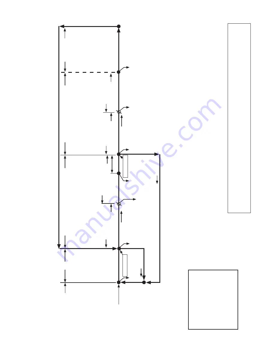
KM-251B
AH Sequence Flo
w Char
t and Component Operation
1.
One Min
ute
Fill Cyc
le
2.
Har
vest Cyc
le
3.
Freez
e Cyc
le
Pump motor stops
for 2 sec.
and then
runs f
or 10 sec.
Cyc
le Steps
FWV
Energiz
ed
LF/S
open
LF/S
closed
Comp
energiz
ed
HGV
energiz
ed
FWV
de-energiz
ed
HWV
energiz
ed
Ther
mistor temp
reaches 48
°F (9°C)
(3.9 k
Ω
or less)
Har
vest timer star
ts
LF/S
open
Comp
contin
ues
HGV
de-energiz
ed
HWV
de-energiz
ed
PM
contin
ues
FMS
energiz
ed
FWV
energiz
ed/
de-energiz
ed
f
or refills only
LF/S
closed
Freez
e cycle
oper
ation tur
ned
ov
er to
LF/S
Comp
contin
ues
HGV
energiz
ed
FMS
de-energiz
ed
LF/S
Chec
k
LF/S
Chec
k
• Maxim
um har
vest w
ater v
alv
e time:
6 min
utes
(HWV time is 6 min
utes or the length of
har
vest min
us 50 sec., whiche
ver is shor
ter
.
PM energiz
es and r
uns f
or the last 50 sec.
of
har
vest.)
• Maxim
um har
vest time:
20 min
utes
Ther
mistor in
control
1 to 3 min
ute timer
in control
• Minim
um freez
e time:
5 min
utes
•
Maxim
um
freez
e
time:
freez
e
timer
setting
• Upper float s
witch used to initiate and
complete w
ater tank refills (9 refills f
or
KM-251BAH)
5 min
ute timer
in control
Lo
w
er float
switch in
control
Initial star
tup alw
ays
begins here
"G" board will ha
ve
5 second dela
y
If
LF/S
is open, compressor stops and cycle retur
ns to 1 min
ute fill
End of 1st
freez
e and
ev
er
y 10th
cycle thereafter
50 sec.
PM
energiz
ed