73
1.
Pa
tte
rn
s
A a
nd
B
- Bin S
w
itch
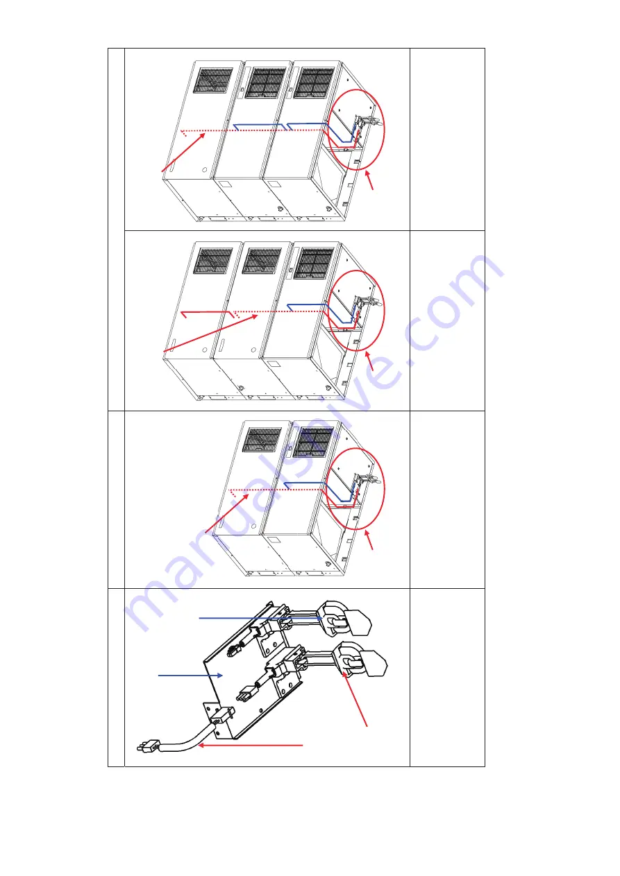
Connections
fo
r I
, I
II,
V
I, a
nd
V
III
As bin switches have dif
ferent contr
ol volt
ages and cannot
be connecte
d, att
ach bin
switch assy sep
arately
.
(
NEW
TYP
E: 5V DC,
OLD
TYPE:
100V AC
)
Det
ail A
Double T
riple
1.
Att
ach 3) bin switch assy to
bracket - bi
n switch of NEW
TYPE.
Then, connect 4) cable B - kit.
1.
Att
ach bracket - bin sw
itch.
2.
C
on
ne
ct
4
) c
ab
le
B
- k
it w
ith
connect
or for bin switch
o
f upper
unit.
1.
Att
ach bracket - bin sw
itch.
2.
C
on
ne
ct
4
) c
ab
le
B
- k
it w
ith
connector for bin switch of middle unit.
3.
N
o
ch
an
ge
in
c
on
ne
ct
io
n
of
upper and
mid
dle unit
s.
1.
Att
ach bracket - bin sw
itch.
2.
Connect 4) cable B - kit with connector for bin switch of upper unit.
3.
No
change
in
connection
of
m
id
dl
e a
nd
lo
w
er
u
ni
ts
.
*1: Connector for bin sw
itch assy is
dif
ferent. (N
EW
TYPE:
2P
connector
, OLD
TYPE: 3P
connector)
Brac
ke
t -
bin
s
w
itch of
N
EW
T
YP
E
4) 4Y51
79G
01
Cable B - kit
3)
3
Y5
24
5A
01
B
in
s
w
itch
as
sy
*
1
*
1
A
NEW
4) 4Y51
79G
01
Cable B - kit
A
4) 4Y51
79G
01
Cable B - kit
NEW
A
4) 4Y51
79G
01
Cable B - kit
NEW
NEW
Bin
sw
itch
as
sy
of NE
W TYPE
Содержание IM-240ANE
Страница 4: ...1 I SPECIFICATIONS 1 DIMENSIONS SPECIFICATIONS a IM 240DNE Air cooled ...
Страница 5: ...2 b IM 240DNE C Air cooled ...
Страница 6: ...3 c IM 240DWNE Water cooled ...
Страница 7: ...4 d IM 240DWNE C Water cooled ...
Страница 8: ...5 e IM 240DWNE R452 Water cooled ...
Страница 9: ...6 f IM 240ANE Air cooled ...
Страница 10: ...7 g IM 240AWNE Water cooled ...
Страница 11: ...8 h IM 240DSNE Remote Air cooled ...
Страница 12: ...9 j URC 240C E 4 Condenser Unit ...
Страница 20: ...17 a CONTROLLER BOARD LAYOUT Main Board Sub Board Combination ...
Страница 37: ...34 2 WIRING DIAGRAM a IM 240DNE C XNE C IM 240DWNE C R452 XWNE C R452 IM 240ANE AWNE ...
Страница 38: ...35 b IM 240DSNE XSNE URC 240C E 4 ...
Страница 69: ...66 Fig 16 Controller Board Board Support Control Box Cover Screw ...


