background image

Aluminium 

clips

The aluminium clips are placed on the piston 

rods of hydraulic cylinders, depending on the 

operating states, see chapter 

Operation

.

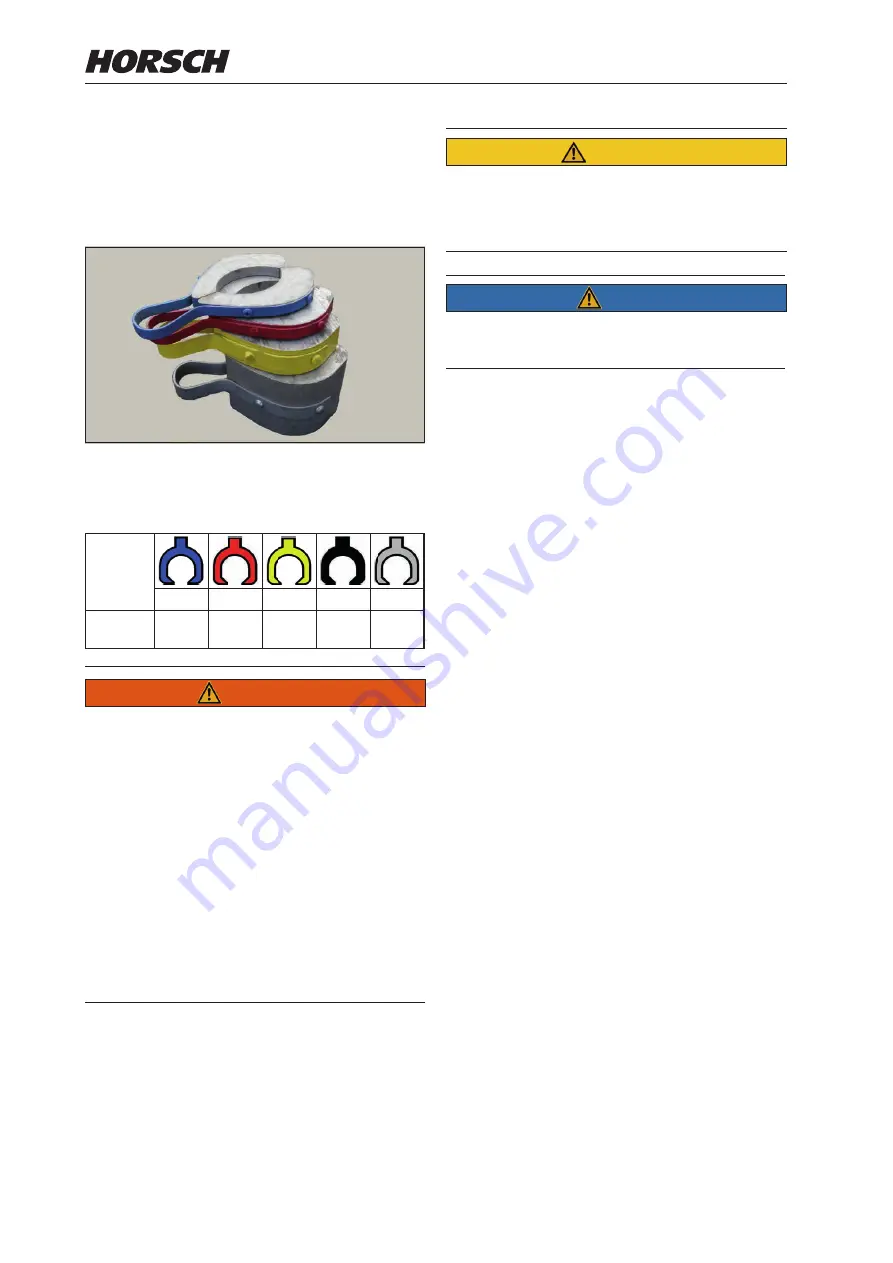
Different aluminium clips

The thickness of the clips differs according to 

colour:

Colour

blue

red

yellow black

silver

Thick-

ness

7 mm

10 mm 19 mm 30 mm 50 mm

 WARNING

Risk of injury on the hydraulic cylinders!
Limbs may be pinched or crushed by uninten-

tional retraction of the piston rods.


¾

When attaching or removing the clips  the 

machine must be parked with the parking 

brake pulled. 

Nobody may be about in the area of the tractor 

cab at this time.


¾

Lock control units mechanically or electrically, 

depending on the version.


¾

Make sure when placing or removing clips 

that the control units are not operated by any 

other person.


CAUTION

Danger of damage to the packer frame.


¾

Depending on the design, do 

not

 remove any 

fixed clips or depth limitations!


NOTE


¾

Pay attention to the ratio on the machine, see 

Depth setting

.

38

39

Содержание Tiger 3 AS

Страница 1: ...TRANSLATION OF THE ORIGINAL OPERATING INSTRUCTIONS READ CAREFULLY PRIOR TO STARTING UP KEEP OPERATING INSTRUCTIONS IN A SAFE PLACE ART ISSUE OPERATING INSTRUCTIONS 60007906 05 2019 Tiger MT ...

Страница 2: ......

Страница 3: ... 0 9431 7143 9200 E mail info horsch com Customer No HORSCH Confirmation of receipt of machinery Warranty claims become only effective when the first use of the machine is reported to HORSCH Maschinen GmbH within a week At www horsch com under SERVICE PARTNERBEREICH an interactive PDF form is available for down load for this purpose not available in all languages By clicking on Send depending on t...

Страница 4: ...häftsführer Leiter Forschung und Entwicklung Tiger 5 MT Tiger 6 MT Tiger 8 MT Grubber Tiger 3 MT Tiger 4 MT Tiger 4 MT starr Translation of EC Declaration of Conformity Directive 2006 42 EC The manufacturer HORSCH Maschinen GmbH Sitzenhof 1 D 92421 Schwandorf hereby declares that the product Type this declaration refers to conforms with all relevant fundamental health and safety requirements of th...

Страница 5: ......

Страница 6: ...ses 37 Aluminium clips 38 Lighting 39 Instruction stickers 40 Operation 44 Commissioning Tractor change 44 Connecting Transport position 44 Folding 46 Unfolding 47 Folding in 47 Parking 48 Folding Tiger 5 8 MT with DuoDrill 49 Setting the transport height 49 Depth setting 51 Basic setting 51 Tine field depth setting 51 DiscSystem depth setting 51 Pendulum compensation double RollPack packer 52 Che...

Страница 7: ...3 ...

Страница 8: ...ed proper acceptance of the machine The warranty period starts with the date of delivery We reserve the right to alter illustrations as well as technical data and weights contained in these operating instructions for the purpose of improv ing the machine The illustrations in these operating instructions show different versions of the implement and different equipment variants Notes on representati...

Страница 9: ...ng Warranty claim forms must be submitted to HORSCH through your local HORSCH sales partner Consequential damage The machine has been manufactured by HORSCH with greatest care However despite the intended use deviations in placing quantity up to total failure may be caused by e g damage caused by external influences wear of wear items missing or damaged cultivation tools Incorrect travel speeds in...

Страница 10: ...ning extremely compacted field areas can be recognised by the constant jump ing up of the tines when traversed or by the repeated shearing off of the tines with shear bolt protection operating the machine while persons are still in the danger zone this includes in particular transport rides on the machine carrying out maintenance and or repair work on a machine that has not been shut down or is no...

Страница 11: ...perating instructions accessible for the machine operator ensure that the operator has read and under stood the operating instructions Groups of operators Persons who work with the machine must have been trained for the different activities involved Instructed operators These persons must have been trained for their respective activities by the owner or other qualified experts This refers to the f...

Страница 12: ...or weight For machines without brake select the weight of the tractor and the speed so that the ma chine can be managed securely under all conditions Remember the extended breaking distance For road transport the machine must be set to transport position The machine must be folded up and secured see chapter Folding in Connecting and Transport position Clean soil from the folding areas before fold ...

Страница 13: ...juries The following machine parts are particularly important for safety Hydraulics Brakes if available Connecting features Protective features Lighting If in doubt about the safety relevant status of the machine e g in case of leaking operating fluids visible damage or unexpected changes in travel behaviour Immediately shut down and secure the ma chine If possible locate and rectify the faults by...

Страница 14: ...ely Secure and lock the control unit on the tractor if not in use Replace hydraulic hoses at the latest after six years see Maintenance overview Pressure accumulator The hydraulic system is equipped with pressure accumulators Observe the regulations applying at the location of use during operation The owner is solely responsible for complying with them Do not open or work welding soldering drill i...

Страница 15: ...and when jumping Do not touch the outside of the machine Move away from the machine with short step ping strides Technical limiting values If the technical limiting values of the machine are not complied with the machine may sustain damage This can lead to accidents with severe or even fatal physical injuries The following technical limiting values are of particular importance for safety permissib...

Страница 16: ...als such as hydraulic oil lubri cants etc can damage the environment and the health of persons Do not allow operating materials to drain out into the environment Pick up drained operating materials with ab sorbent material or sand fill it into a leak tight container and dispose of in accordance with statutory regulations Retrofitting and conversions Structural changes not approved by HORSCH may af...

Страница 17: ...The ground connection must be as close as possible to the welding point Before cleaning the machine with high pres sure cleaner cover all openings which should stay clear of water steam or cleaning agents for reasons of safety or operation Do not aim the water jet directly on electric or electronic components or bearings When cleaning with high pressure cleaning equipment or steam jet keep a dista...

Страница 18: ...oticed Failing to pay attention to the danger zone can result in severe or even fatal physical injuries Do not stand under lifted loads Lower such loads to the ground first Instruct persons to leave the danger zone around the machine and tractor before any machine movements Before working in the danger zone of the ma chine or between machine and tractor Shut down the tractor This also applies for ...

Страница 19: ...ma chine the operating instructions must be read and followed 00380055 Caution for fluids spraying out under high pressure follow the notes in the operating instruc tions 00380133 Never reach into areas where there is a risk of crushing as long as parts could still be mov ing 00380134 Stay clear of the operating range of foldable machine parts 00380135 When connecting the machine and when operatin...

Страница 20: ... 00381116 Keep sufficient safety distance to the slewing range of the machine 00381117 The pressure accumulator is charged with gas or oil pressure Dismantle and repair only in strict compliance with the instruc tions in the technical manual 00381135 Loading hook hook the load suspension gear chains ropes etc into this loading hook during loading Jack lifting point area where the jack must be atta...

Страница 21: ...Position of safety stickers depending on equipment Safety stickers with the addition 2x can be found on either side of the machine Tiger 8 MT 17 ...

Страница 22: ...r or low loader The permissible dimensions and weights for transport must be complied with The tractor must be large enough so that sufficient steering and braking abilities are ensured If the machine is hitched up in two point mode the tractor link arms must be blocked against swinging sideways On a trailer or low loader the machine must be secured with tensioning straps or other means Attach lif...

Страница 23: ...kg 4 215 5 525 6 575 Number of discs in DiscSystem 14 18 20 Space between discs cm 38 40 50 40 Number of tines 7 9 9 Tine spacing in row cm 86 94 94 Groove spacing cm 43 47 47 Frame height mm 850 850 850 Tyre packer size Ø cm 7 50 16 AS 78 cm or 210 95 24 AS 100 cm Tyre packer 210 95 24 AS not with 4 MT rigid Tyre size Slewing undercarriage Ø cm 400 60 15 5 445 65 R22 5 Double RollPack packer Ø cm...

Страница 24: ...Groove spacing cm 45 5 48 45 Frame height mm 850 850 850 Tyre packer size Ø cm 7 50 16 AS 78 cm or 210 95 24 AS 100 cm Tyre size Slewing undercarriage Ø cm 445 65 R22 5 Double RollPack packer Ø cm 62 62 62 SteelFlex Packer Ø cm 58 60 Design related top speed Specification in type approval with levelling discs 2 row Ø 46 cm NOTE Deviations due to technical further development reserved The weight of...

Страница 25: ...in Germany SN Sitzenhof 1 D 92421 Schwandorf www horsch com A 3 A 2 A 1 A 0 kg Maschinen GmbH kg kg kg kg T 3 T 2 T 1 B 1 B 2 B 3 B 4 Vehicle class Model designation Serial number Year of construction Type approval number Vehicle identification number VIN Technically permissible total weight permissible drawbar load Technically permissible axle load axles 1 2 3 21 ...

Страница 26: ...Ø 50 mm Adjustable drawbar Drawbar eye Ball and socket joint Drawbar eye Ø 51 mm Ball head K 80 Tiger 5 MT 6 MT 8 MT Tractor link arm Cat III III IV IV Cat III III IV IV Cat III III IV IV Adjustable drawbar Drawbar eye Bolt Ø 50 70 mm Bolt Ø 50 70 mm Bolt Ø 70 mm Adjustable drawbar Drawbar eye Ball and socket joint Drawbar eye Ø 51 71 mm Drawbar eye Ø 51 71 mm Drawbar eye Ø 71 mm Ball head K 80 K ...

Страница 27: ...ximum system pressure 210 bar Oil grade Mineral hydraulic oil Number of dual acting control units Tiger 3 MT 4 MT rigid 4 MT Tractor link arm hitching 2 1 with bout marker 3 1 with bout marker 3 1 with bout marker Swinging drawbar hitching 4 1 with bout marker Tiger 5 MT 6 MT 8 MT Tractor link arm hitching 3 1 with bout marker Swinging drawbar hitching 4 1 with bout marker 4 Brake connections Pneu...

Страница 28: ...otal weight of rear implement In case of towed machines Maximum permissible drawbar load for road transport GV Total weight of front implement a Distance from centre of gravity of front implement front ballast to middle of front axle b Tractor wheel base c Distance from middle of rear axle to middle of tractor link arm ball In case of towed machines Distance from middle of rear axle to middle of h...

Страница 29: ...d from the operating instructions of the tractor into the table GH c d TV b 0 2 TL b a b GV min GV a TH b x TL b b c d GH min GV a b TV b GH c d b Tv tat 4 Calculation of the actual total weight Enter the result of the calculated total weight and the permissible total weight from the operating instructions of the tractor into the table 5 Calculation of the real rear axle load Enter the result of t...

Страница 30: ...rview Tiger 6 MT 1 Drawbar tractor link arm hitching 2 DiscSystem 2 row 3 Tine field 2 row 4 Levelling discs 5 Tyre packer here 7 50 16 AS Ø 78 cm 6 TopRing packer option 7 Lighting 8 Packer cylinder 1 2 3 4 5 6 7 8 26 ...

Страница 31: ...ve been de pressurized on both machine and equipment sides NOTE Operate the machine with mineral based hydraulic oil Do not mix mineral oils with organic or ester oils The hydraulic circulation of the tractor must contain mineral based hydraulic oil Oil purity acc to ISO 4406 18 16 13 Always plug in all hydraulic lines Otherwise components may get damaged because of interrelated functions Ensure c...

Страница 32: ...ydraulic cylinder Lift Lower 6 Hydraulic cylinder levelling discs 7 Lock valve levelling discs 8 Hydraulic connection DiscSystem 9 Lock valve double 90 10 Pressure gauge DiscSystem 11 Pressure accumulator 12 Hydraulic cylinder DiscSystem Tiger 3 MT DiscSystem V1 V2 C1 00110326 C2 8 9 10 11 12 12 Tiger 3 MT Lifting lowering 1 3 5 5 6 7 2 4 28 ...

Страница 33: ...Connection lift TopRing Packer 6 Hydraulic cylinder Drawbar 7 Three way rotary spool valve 8 Hydraulic cylinder Folding 9 Connection folding in drawbar option 10 Connection unfolding drawbar option 11 Lock valve double 90 12 Lock valve single 90 13 Lock valve lighting 14 Connection lower TopRing Packer 15 Hydraulic cylinder lift lower outside 16 Hydraulic cylinder lift lower inside 17 Hydraulic cy...

Страница 34: ...t TopRing Packer 5 Three way rotary spool valve 6 Hydraulic cylinder Folding 7 Connection folding in drawbar option 8 Connection unfolding drawbar option 9 Lock valve double 90 10 Lock valve single 90 11 Lock valve lighting 12 Connection lower TopRing Packer 13 Hydraulic cylinder lift lower outside 14 Hydraulic cylinder lift lower inside 15 Hydraulic cylinder levelling discs 16 Lock valve levellin...

Страница 35: ...ake valve 5 Connection lift TopRing Packer 6 Hydraulic cylinder Drawbar 7 Three way rotary spool valve 8 Hydraulic cylinder Folding 9 Connection folding in drawbar option 10 Connection unfolding drawbar option 11 Lock valve double 90 12 Lock valve single 90 13 Connection lower TopRing Packer 14 Hydraulic cylinder lift lower outside 15 Hydraulic cylinder lift lower inside 16 Hydraulic cylinder leve...

Страница 36: ...e valve 4 Connection lift TopRing Packer 5 Three way rotary spool valve 6 Hydraulic cylinder Folding 7 Connection folding in drawbar option 8 Connection unfolding drawbar option 9 Lock valve double 90 10 Lock valve single 90 11 Connection lower TopRing Packer 12 Hydraulic cylinder lift lower outside 13 Hydraulic cylinder lift lower inside 14 Hydraulic cylinder levelling discs 15 Lock valve levelli...

Страница 37: ...System 4 Pressure accumulator 5 Hydraulic cylinder DiscSystem 1 Hydraulic connection Lift Lower 2 Connection lift TopRing Packer 3 Lock valve double 90 4 Connection lower TopRing Packer 5 Hydraulic cylinder Lift Lower 6 Hydraulic cylinder levelling discs 7 Lock valve levelling discs Tiger 4 MT rigid lifting lowering 1 5 3 5 6 6 4 7 2 33 ...

Страница 38: ...2 C1 00110326 C2 Tiger 4 MT rigid DiscSystem 1 3 2 4 4 5 5 5 5 1 Hydraulic connection DiscSystem 2 Lock valve single 180 3 Pressure gauge DiscSystem 4 Pressure accumulator 5 Hydraulic cylinder DiscSystem 34 ...

Страница 39: ...ift TopRing Packer 5 Three way rotary spool valve 6 Hydraulic cylinder folding 7 Connection folding in drawbar option 8 Connection unfolding drawbar option 9 Lock valve double 90 10 Lock valve single 90 11 Connection lower TopRing Packer 12 Hydraulic cylinder lift lower outside 13 Hydraulic cylinder lift lower inside 14 Hydraulic cylinder levelling discs 15 Lock valve levelling discs 35 ...

Страница 40: ...ection lift TopRing Packer 6 Hydraulic cylinder drawbar 7 Three way rotary spool valve 8 Hydraulic cylinder folding 9 Connection folding in drawbar option 10 Connection unfolding drawbar option 11 Lock valve double 90 12 Lock valve single 90 13 Connection lower TopRing Packer 14 Hydraulic cylinder lift lower outside 15 Hydraulic cylinder lift lower inside 16 Hydraulic cylinder levelling discs 17 L...

Страница 41: ...ic cou plings indicate the function of the respective hoses Lift lower Unfolding Folding in Working depth Drawbar Bout marker NOTE The following hydraulic movements are carried out via the hoses marked with Lift Folding in Retraction of cultivation tools Fan flow 37 ...

Страница 42: ... crushed by uninten tional retraction of the piston rods When attaching or removing the clips the machine must be parked with the parking brake pulled Nobody may be about in the area of the tractor cab at this time Lock control units mechanically or electrically depending on the version Make sure when placing or removing clips that the control units are not operated by any other person CAUTION Dan...

Страница 43: ...inker left 2 54 g 3 31 white Earth 4 R green Blinker right 5 58 R brown Rear light right 6 54 red Brake light 7 58 L black Rear light left WARNING Traffic accidents caused by defective lighting Ensure cleanliness and tight fit of the plug and socket connections Check the lighting before setting off Check warning boards and lighting equipment for cleanliness Check the plug and socket connections on...

Страница 44: ...tc into this loading hook during loading Loading work only by operators trained by HORSCH Tighten with the appropriate torque Check the tyre pressure at regular inter vals adapt if necessary see mainte nance overview Attach the scales here when calibrating With DuoDrill equipment insert the alumini um clips on the piston rods before folding in M in 50m m Maximum tyre pressure 2 6 bar 2 6 bar 4 9 b...

Страница 45: ...n wir uns alle Rechte vor Werkstück kanten DIN 6784 Gewicht kg 3D A4 Bemaßungen in mm c 3D erstellt 16 10 2015 ludwig b auf Solid Edge 13 02 2007 GM a Umstellung 13 08 2003 GM 2 1 20 11 1998 Muck Aufkl Rücklaufdruck max 5bar 00380242 0 006 kg Allgemein toleranz ISO 2768 m Horsch Maschinen GmbH Änderungen sind untersagt Landwirtschaft aus Leidenschaft HORSCH Maschinen GmbH Sitzenhof 1 92421 Schwand...

Страница 46: ...e 00380900 Atteler à un tracteur dont le relevage est équipé de dispositifs de blocage latéraux et verticaux Pour circuler sur la route respecter la hauteur d attelage spécifiée dans la notice d utilisation et bloquer le relevage O O Block SteelDisc Packer lifting lowering 00385764 Swinging drawbar hitching cat 5 KAT 5 00380579 42 ...

Страница 47: ...ollision for machines with DuoDrill Min 100 mm Risk of collision Tiger 4 6 with SteelDisc Packer 00385483 4x Min 100 mm Tightening torque packer connection 00380547 Risk of collision Tiger 4 8 with Pronto TD 43 ...

Страница 48: ...omply with the accident prevention instruc tions Connecting Transport position The machine must be properly connected to a tractor before any machine movements DANGER Serious accidents from loss of stability Machines with pneumatic brake Do not move the machine without a brake line connected When connecting always connect the yellow connection brake line first NOTE Check all plug and socket connec...

Страница 49: ...rol unit to the floating position 3 Machines with swinging drawbar hitching Switch the drawbar control unit to the locked position and then open the lock valve on the drawbar Set the height of the drawbar via the drawbar control unit WARNING Danger of severe injury caused by the dropping falling drawbar Instruct persons to leave the danger zone Never stand under the drawbar 4 Move the tractor furt...

Страница 50: ... is not exceeded 13 Lower the machine to the aluminium clips 14 Lock and secure the control units Folding WARNING Dropping or lowering machine parts can cause severe crushing injuries etc No persons may stay under raised machine parts Order persons to leave the danger zone around the machine Make sure before fold ing that no persons are present in the danger zone Comply with the accident preventio...

Страница 51: ...upward and insert the large silver coloured clips 350 mm CAUTION Danger of machine damage caused by colli sions Always turn the slewing undercarriage com pletely down before unfolding the machine Carry out the unfolding process with caution and stop all machine movements in the event of imminent collisions 5 Unfolding the machine 6 Open the lock valve for TopRing packer and disc levelling Folding ...

Страница 52: ... the control unit Parking Initial position The machine is folded in and connected to the tractor 1 Lift the machine completely 2 Machines with swinging drawbar hitching Fill the piston rod of the drawbar cylinder with aluminium clips 3 Unfold the support 4 Machines with swinging drawbar hitching Remove the aluminium clips again from the drawbar cylinder WARNING Danger of severe injury caused by th...

Страница 53: ...e cylinders onto the clips B Completely retract the cylinders for lifting lowering Machines with small tyre packer Remove the border disc of the levelling discs Completely retract the cylinders for lifting lowering Machines with large tyre packer Completely retract the cylinders for lifting lowering Folding Tiger 5 8 MT with DuoDrill With the cultivator is equipped with a DuoDrill drill unit an al...

Страница 54: ... lower DiscSystem working depth Drawbar Position Control unit Floating position Locked position Supply Unfolding Folding Lift lower DiscSystem working depth Drawbar Undercarriage Position of control units during road travel Machine with tyre packer Machine with slewing undercarriage 50 ...

Страница 55: ... with tractor link arm hitching adjust the height of the tractor link arm hitch ing until the machine is aligned horizontally Fix the height of the tractor link arm position during work 3 Lower the machine with pressure onto the aluminium clips 4 Switch the control unit to the floating position when working in the field DiscSystem depth setting Perform setting of the DiscSystems in the field Start...

Страница 56: ...lic cylinders of the outer packers determine the basic set ting of the two packer rollers The lower work is done with the Tiger the more additional aluminium clips have to be inserted on the cylinders Aluminium clips of the same colour and number must be inserted on all cylinders Hydraulic cylinder undercarriage outside Hydraulic cylinder undercarriage centre The front packer roller should run som...

Страница 57: ...ower DiscSystem working depth Drawbar Position Control unit Floating position Locked position Supply Unfolding Folding Lift lower DiscSystem working depth Drawbar Undercarriage Position of control units during use in the field Machine with tyre packer Machine with slewing undercarriage 53 ...

Страница 58: ...work Checks before and during use on the field Machine Have the hydraulic lines been connected without being mixed up by mistake Does the lighting for road travel work Have the bout markers been set to the cor rect length Has the machine been levelled in working position and the working depth correctly adjusted Cultivation tools Are coulters harrows and other cultivation tools and optional equipme...

Страница 59: ...ition For trouble free operation it is very important to carry out the necessary work for care and maintenance at the recommended intervals Cleaning Perform regular cleaning and maintenance work in order to maintain the operability of the machine and to achieve optimal performance NOTE Do not clean hydraulic cylinders and bearings with a high pressure cleaner or direct water jet Seals and bearings...

Страница 60: ...als for the necessary main tenance tasks must be adapted accordingly Regular maintenance is the basis for a fully operable machine Properly serviced machines reduce the risk of failing and ensure economical use and operation of the machines Storage If the machine is to be shut down for a longer period of time If possible park the machine under a roof Protect the machine against corrosion For spray...

Страница 61: ...ripping force of approx 800 kg prevents dam age to tines tine holder and coulters Once the tripping force is reached the tine can easily and quickly escape up to 30 cm upwards MulchMix coulter WARNING Danger of injury caused by the machine lower ing Always support the machine with suitable means with any assembly or maintenance work on tines and coulters Secure the lift cylinders with aluminium cl...

Страница 62: ...field to check the working quality of the levelling discs The soil shall be levelled in front of the packer to achieve uniform consolidation If a heap of soil is created behind the discs they must be set deeper If a furrow is created behind the discs they must be set more shallow 4 Raise the machine to adjust the levelling discs and to relieve the bolts for depth ad justment 5 Insert the bolts int...

Страница 63: ...discs must be removed for transport on public roads not to exceed the maximum permitted transport height NOTE Move the levelling discs again to working position before use in the field Maintenance Bearings are oil filled and therefore maintenance free Levelling discs Check the discs regularly for clearance leak tightness of the bearings and true running Notes on servicing The mechanical seals are ...

Страница 64: ...g screws again A Border discs height adjustment Angle of attack adjustment of the discs The angle of attack of the discs must be ad justed to the working speed and the amount of earth and harvest residues thrown up Remove the screw B and loosen screw C Set the desired angle and tighten the screws B and C again B C Border disc angle adjustment Tiger 3 MT Fold down the border discs before use when c...

Страница 65: ...ree Check the discs regularly for clearance leak tightness of the bearings and true running DiscSystem The 2 row DiscSystem of the Tiger MT is located in front of the tine field The large serrated discs cut large quantities of harvest residues and are also suitable for use on long fibre residues such as maize straw The preparation work of the DiscSystem ensures blockage free working of the tines a...

Страница 66: ...ansport undercar riage during road travel The packer is swivelled down for use in the field A B A Double RollPack Packer B Transport undercarriage Insert one large silver aluminium clip 350 mm on each of the two hydraulic cylinders after swivelling down the packer Aluminium clip on the cylinder of the packer 62 ...

Страница 67: ...ne 2 Always lower the machine with pressure so that the TopRing packer is guided in the soil with the set pressure 3 Switch the control unit to floating position when all packer cylinders rest fully on the aluminium clips If the TopRing packer is not required it can be blocked in transport position with the lock valve NOTE The pressure control valve on the packer is set at the factory and must not...

Страница 68: ...packer shafts for free rotation Adjust the scrapers as necessary Rear drawing hook A drawing hook can be attached to the Tiger MT to connect working implements such as a HORSCH Optipack The hook is designed for HORSCH implements Other machines with a drawbar load of up to 500 kg can also be hitched up Drawing hook The rear drawing hook is flange mounted to the rear of the main frame In addition hy...

Страница 69: ...utor It mainly consists of the distributor tower the hose system and the fer tiliser tubes on the tine bars Fertiliser is directed to the tines via the distributor tower and the hose system 1 1 2 3 Tiger with fertiliser distributor 1 Hose system 2 Distributor tower 3 Fertiliser tubes on tines Maintenance Check the distributor regularly for foreign objects Check hoses and distributor cover for firm...

Страница 70: ...bout marker Tiger 4 MT 400 cm 2 200 cm 200 cm 12 cm 212 cm The bout markers must be set to 212 cm meas ured from the middle of the outermost tine Setting dimensions Tiger 4 MT 212 cm Tiger 5 MT 252 cm Tiger 6 MT 312 cm Adjusting the fertiliser placement The fertiliser placement optionally takes place by the coulter into the ground behind the coulter on the surface of the field approx half each int...

Страница 71: ...hydraulic connections and one pressureless return flow are available on the connection to operate the hooked up machine DANGER Danger of serious traffic accidents Never connect machines to the Tiger in public road traffic Aggressiveness of bout markers A Bout marker disc setting Adjust the aggressiveness of the bout markers according to the soil conditions Loosen the hexagon screws A for this pur ...

Страница 72: ...ecessary In use Hydraulics WARNING Lower all hydraulically lifted parts e g wings packer undercarriage etc to the ground before performing any work on the hydraulic system Depressurise the hydraulics on the tractor and implement side Empty the pressure accumulators Risk of scalding Allow hydraulic oil and hydraulic components heated during operation to cool down before any work on the hydraulic sy...

Страница 73: ...l and socket coupling Before connecting Clean ball and spherical cap daily Replace the foam ring if damaged and or heavily soiled daily Place the foam ring daily Check ball and spherical cap for wear The wear limit has been reached when the gauge rests fully on the ball or enters the spherical cap Hold the gauge lengthwise toward the direction of travel Direction of travel Ball OK Ball worn 40 h D...

Страница 74: ...ght of ring h 54 0 51 5 Fastening Check mounting screws for firm seat 560 Nm 40 h Wear a h b Replace the component concerned if one of the wear limits has been exceeded or fallen short of workshop work 40 h Designation Nominal dimension mm Wear dimension mm ø eye a 71 73 Width of ring b 25 5 23 0 Height of ring h 54 0 51 5 Machine Frame frame connection parts Check condition and firm seating 40 h ...

Страница 75: ...ck clearance and adjust if necessary must only be carried out by an expert workshop 120 h 6 months Brake system Check setting and function daily Drain air reservoir daily Check brake lines and hoses for damages crushing points and kinks daily Clean the pipe filter annually as necessary Safety installations Lighting and warning boards Check condition and function daily Warning and safety stickers C...

Страница 76: ... 1 1 1 daily Packer arm bearing 2 2 6 6 6 6 daily Folding pin support 4 4 4 4 40 h Disc axle 4 4 8 8 8 40 h Optional equipment Bout marker hinge bearing 2 2 2 2 2 40 h Eye and ball head hitching spherical cap 1 1 1 1 40 h Ball and socket joint drawbar eye 1 1 1 1 40 h Lubrication points with the addition 2x can be found on either side of the machine Two point trailer hitch Swinging drawbar hitchin...

Страница 77: ...he disposal of auxiliary and operating me dia as well as other chemicals you must strictly comply with the specifications in the respective safety data sheets Decommissioning If the machine is no longer suitable for use and needs to be disposed of it must be decommis sioned All machine parts must be separated by material and passed on to environmentally friendly waste disposal or recycling Attenti...

Страница 78: ...2 4 0 6 1 8 9 10 4 6 1 00 5 5 6 8 10 4 15 3 17 9 7 1 00 9 3 11 5 17 2 25 30 8 1 25 13 6 16 8 25 37 44 8 1 00 14 5 18 27 40 47 10 1 50 26 6 33 50 73 86 10 1 25 28 35 53 78 91 12 1 75 46 56 86 127 148 12 1 25 50 62 95 139 163 14 2 00 73 90 137 201 235 14 1 50 79 96 150 220 257 16 2 00 113 141 214 314 369 16 1 50 121 150 229 336 393 18 2 50 157 194 306 435 509 18 1 50 178 220 345 491 575 300 20 2 50 ...

Страница 79: ...0 31 2 35 2 44 7 50 2 7 16 11 1 33 9 36 6 50 2 55 6 70 5 78 6 1 2 12 7 47 5 54 2 77 3 86 8 108 5 122 0 9 16 14 3 67 8 81 3 108 5 122 0 156 0 176 3 5 8 15 9 95 0 108 5 149 1 169 5 216 0 244 0 3 4 19 1 169 5 189 8 271 1 298 3 380 0 427 0 7 8 22 2 176 3 196 6 433 9 474 5 610 0 678 0 1 25 4 257 6 278 0 650 8 718 6 915 2 1017 1 1 8 28 6 359 3 406 8 813 5 908 4 1302 1458 1 1 4 31 8 508 5 562 7 1139 1261...

Страница 80: ...t 66 Foreword 4 H High pressure cleaner 55 Hold down 70 Hydraulics 10 68 69 70 I Installation 18 L Length 19 20 Levelling discs 58 Liability 4 Lighting 39 Lubrication 55 Lubrication points 72 M Maintenance 13 55 68 Maximum speed 8 19 20 O Operator 7 Overhead lines 11 P Plug 39 Pressure accumulator 10 Protective outfit 8 Q Qualification of personnel 7 R Ratio 38 Recycling 73 Retrofits 12 Road trans...

Страница 81: ...Tines 57 Tractor change 44 Tractor link arm 22 Traffic 8 Transport 8 Transport width 8 Type approval 8 U Use in the field 11 W Warranty 4 Waste disposal 73 Wheel nuts 68 Wheels brakes 71 Width 19 20 Working width 19 20 77 ...

Страница 82: ......

Страница 83: ...chnical specifications and pictograms are approximate and for information only Subject to technical product revisions HORSCH Maschinen GmbH Sitzenhof 1 92421 Schwandorf Tel 49 94 31 7143 0 Fax 49 94 31 7143 9200 E Mail info horsch com ...

Отзывы: