


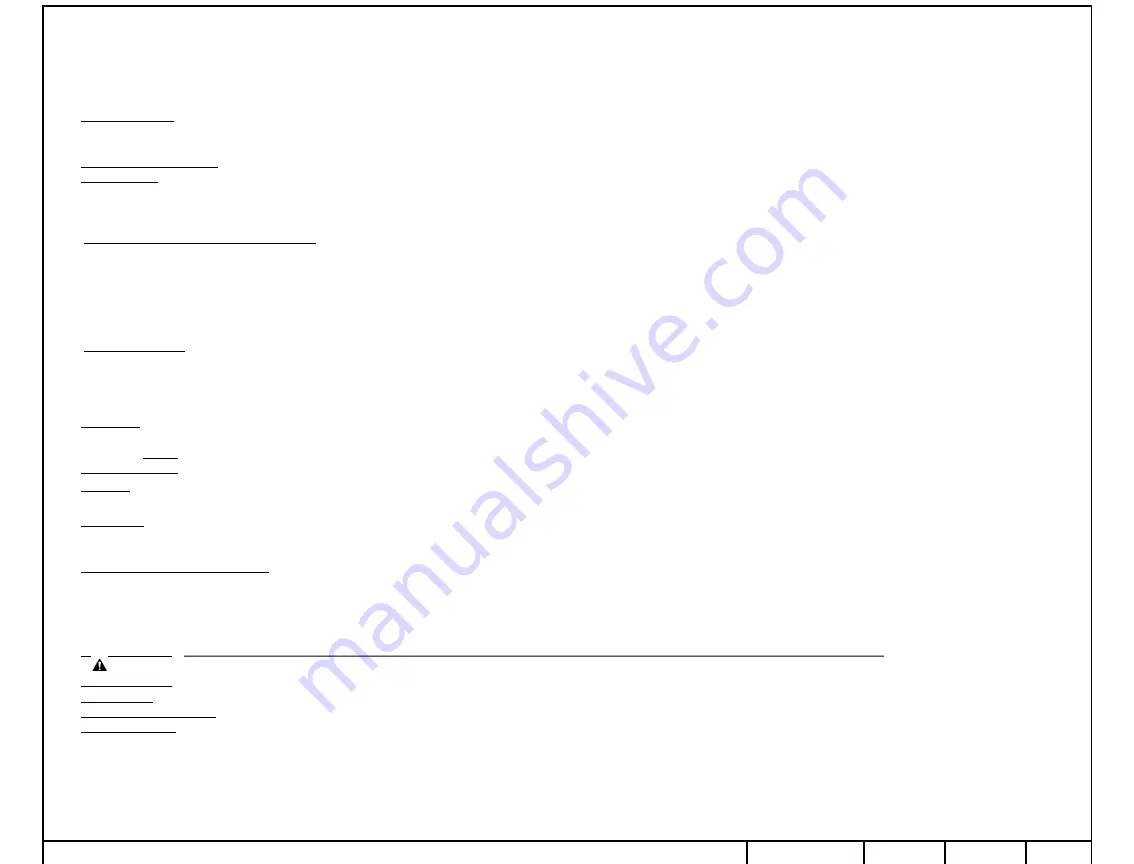
Installation Instructions
2019 Hyundai Elantra
*Note: If rear bumper fascia has a lower panel that can be removed see 2018 Hyundai Elantra installation instructions.
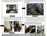
1.
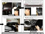
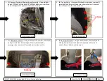
Remove Taillights
–
Open trunk. Remove access panel from behind taillight. Using a 10mm socket, remove (2) hex nuts that secure taillight. Unplug the electrical connector and push wiring
with rubber grommet through hole in body. Remove the taillight by gently pulling horizontally rearward. Repeat on other side of vehicle.
Note
: During taillight removal, filler panel on side of light assembly may detach from taillight. Ensure panel is reinstalled before taillights are reinstalled on vehicle.
2.
Remove Underbody Panel
–
Using a 10mm socket and flat head screwdriver, remove (4) hex nuts and (3) push pin rivets from underbody panel on the driver's side of vehicle.
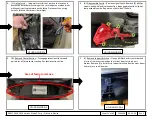
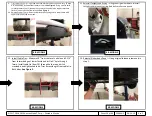
3.
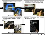
Lower Exhaust
–
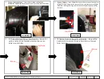
Using an exhaust hanger removal tool (or pry bar) remove the rubber isolators from hangers.
Note:
Support the exhaust before lowering.
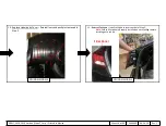
Note:
Removal of the heat shield is not required but can be removed to assist with modification. Cut or bend the area around the rearmost stud to make clearance for the hitch arm.
Make sure to leave the hole in the heat shield so that it may be reattached. If removed, modify and reattach. (See Figure 5)
4.
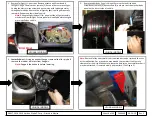
Remove Fascia and Bumper Beam Assembly
–
a)
Under taillight:
Remove (2) push pin rivets and (1) phillips head screw from fascia under taillight area. Repeat on other side of vehicle.
b)
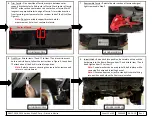
Fender wells:
Using a phillips head screw driver, remove (3) screws and one 8mm hex head screw from wheel well liner and fascia. Repeat on other side of vehicle.
c)
Underside of fascia:
Using a flat head screw driver, remove (3) push pin rivets from bottom edge of fascia. (2) located by passenger side rear tire, (1) located by driver side rear tire.
d)
Bumper fasteners:
Using a 12mm socket, remove (2) bolts holding bumper beam to end panel. Repeat on other side of vehicle. Return bolts to vehicle owner.
e)
Unclip fascia:
Using a plastic trim tool, remove the fascia and bumper beam assembly starting at the outer edges near wheel wells while gently pulling rearward on the fascia.
Disconnect the wiring harness, located near driver side taillight.
5.
Disassemble Fascia
–
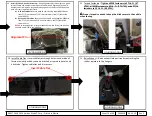
a)
Remove signal lights:
Remove (4) phillips screws, unhook electrical connection, disengage retention clip. Set lamp assembly aside. Repeat on other side of vehicle.
b)
Remove center section:
Disengage retention clips around perimeter of fascia center section. Set fascia section aside.
c)
Remove support brackets:
Using a phillips head screw driver and flat head screwdriver, remove screw and push pin rivet from fascia support bracket. Remove (3) plastic fascia
support brackets from bumper beam and return to vehicle owner.
6.
Trim Fascia
–
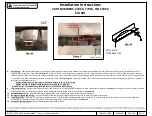
On underside of fascia, measure between outer support bracket holes. Mark center of fascia. Mark 3” wide section centered on
the
center line of fascia. Mark 5” long section
perpendicular to edge of fascia. Trim marked section from fascia to give clearance for the receiver tube of the hitch. (See Figure 3)
Note:
Do not use middle support bracket hole for measurement, hole is not centered in fascia.
7.
Reassemble Fascia
–
Reinstall center section of fascia and signal lights removed in Step 5.
8.
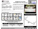
Fish Wire
–
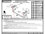
Attach items
j
and
k
to item
n
and insert in access hole in vehicle frame, follow the instructions in Figure 2. Leave item
n
attached until the hitch is raised into position.
Note
: If plastic caps are covering the access hole remove and return to vehicle owner.
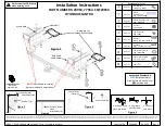
9.
Install Hitch
–
Raise hitch into position, be careful not to push the hardware into the frame. Remove item
n
and attach item
l
and hand tighten item
m
to item
j
.
Note:
Conical washer can be used to hold bolt in place while removing fish wire and installing hex nut.
Note:
Use second person or jack to steady hitch while lifting into position and hold until all bolts are installed.
10. Install Fascia and Bumper Assembly
–
Using alignment pins in bumper as a guide, reinstall fascia and bumper assembly onto vehicle. Hand tighten bolts to hold bumper and hitch in place. Align
and re-engage all clips. Reinstall all screws and push pin rivets removed from fascia.
a)
USA built models:
Secure hitch to vehicle using supplied M10 bolts, item
o
(2) per side and 7/16” conical washers, item
l
(teeth side toward hitch).
b)
Korean built models:
Secure hitch to vehicle using supplied M8 bolts, item
p
(2) per side and 3/8” conical washers, item
q
(teeth side toward hitch).
Note:
Use second person or jack to steady hitch while lifting into position and hold until all bolts are installed.
11. Torque Fasteners
–
Tighten all M8 fasteners to 27 Lb-Ft. (37 N*M), all M10 fasteners to 42 Lb.-Ft. (57 N*M), and all 7/16 fasteners to 50 Lb.-Ft. (68 N*M).
Proper torque is needed to keep the hitch secure to the vehicle when towing.
12. Install Cable Ties
–
Insert cable ties through holes in underside of fascia previously used by support brackets, wrap cable ties around hitch tube. Tighten cable ties and trim excess.
13. Raise Exhaust
–
Raise exhaust into position by reattaching the rubber isolators to the hangers.
14. Replace Underbody Panel
–
Reinstall nuts and pushpins removed in Step 2.
15. Reinstall Taillights
–
Install taillights in reverse order of Step 1.
Note:
Ensure filler panel is properly installed on each taillight before installing onto vehicle.
Note:
Check hitch frequently, making sure all fasteners and ball are properly tightened. If hitch is removed, plug all holes in trunk pan or other body panels to prevent entry of water and exhaust fumes. A hitch or ball which has been damaged should be removed and replaced. Observe
safety precautions when working beneath a vehicle and wear eye protection. Do not cut access or attachment holes with a torch. This product complies with safety specifications and requirements for connecting devices and towing systems of the state of New York, V.E.S.C. Regulation
V-5 and SAE J684.
©2017, 2018, 2019 Horizon Global™ Corp. –
Printed in Mexico
Sheet 8 of 60
24964NP
06-24-19
Rev. C