
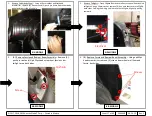


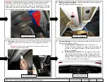

1.
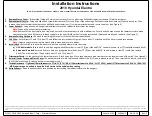
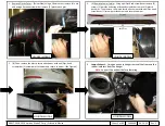
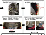
Remove Underbody Panel
–
Using a 10mm socket and flat head screwdriver, remove (4) hex nuts and (3) push pin rivets from underbody panel on the driver
’s
side of the vehicle.
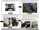
2.
Remove Taillights
–
Open liftgate. Remove small access panel from behind taillights. Using a 10mm socket, remove (4) hex nuts that secure taillights, both sides. Unplug the wiring
and remove the taillights by gently pulling rearward.
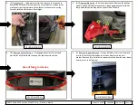
3.
Remove Fascia and Bumper Beam Assembly
–
a)
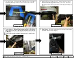
Remove (1) push pin rivet and (1) phillips head screw from fascia under taillight area, both sides.
b)
Using a phillips head screw driver, remove (3) screws from wheel well liner and fascia, both sides.
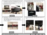
c)
Using a 12mm socket, remove (2) M8 bolts holding bumper beam to end panel, both sides. Return existing M8 bolts to vehicle owner.
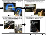
d)
Using a plastic trim tool, remove the fascia and bumper beam assembly starting at the outer edges near wheel wells while gently pulling rearward on the fascia.
Disconnect the wiring harness from fascia if present.
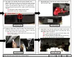
4.
Remove Lower fascia from Upper fascia
–
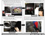
Using a flat head screw driver, remove (2) push pin rivets from bottom edge of fascia, (1) per side. Using a plastic trim tool, unclip all tabs
from lower fascia.
Note:
Lift the foam piece above the bumper beam to gain access to some of the tabs.
5.
Remove Support Brackets
–
Using a phillips head screw driver, remove (2) plastic fascia support brackets from bumper beam and return to vehicle owner.
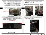
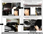
6.
Reinstall Upper fascia
–
Reinstall Upper fascia and bumper beam assembly to vehicle. Be sure to reconnect all wiring.
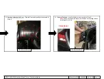
7.
Modify Heat Shield
–
Bend edge of heat shield down near exhaust hanger area to allow hitch side arm to sit flat against bottom of frame on passenger side.
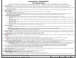
Note:
Check hitch frequently, making sure all fasteners and ball are properly tightened. If hitch is removed, plug all holes in trunk pan or other body panels to prevent entry of water and exhaust fumes. A hitch or ball which has been damaged should be removed and replaced.
Observe safety precautions when working beneath a vehicle and wear eye protection. Do not cut access or attachment holes with a torch. This product complies with safety specifications and requirements for connecting devices and towing systems of the state of New York, V.E.S.C.
Regulation V-5 and SAE J684.
©2017, 2018, 2019 Horizon Global™ Corp. –
Printed in Mexico
Sheet 15 of 60
24964NP
06-24-19
Rev. C
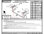
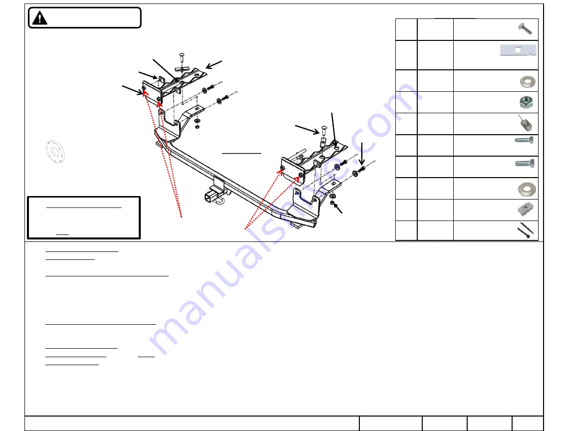
①
Qty. (2)
Carriage Bolt
7/16-14 x 1.75 GR5
②
Qty. (2)
Block
.250 x .875 x 3
P/N
–
HE-2370-000
③
Qty. (6)
Conical Washer 7/16”
P/N
–
01292007
④
Qty. (2)
Hex Nut
7/16-14 GR2
⑤
Qty. (2)
Fish Wire 7/16”
P/N
–
5481
o
Qty. (4)
Hex Bolt
M10-1.25 X 35mm CL10.9
p
Qty. (4)
Hex Bolt
M8-1.25 x 40mm CL10.9
q
Qty. (4)
Conical Washer 3/8”
P/N
–
01292006
r
Qty. (4)
Spacer P/N
–
03060
1.5” x 1.0” x 0.25”
s
Qty. (2)
Cable Ties
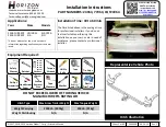
Fastener Kit:
24964F
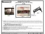
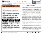
Installation Instructions
PART NUMBERS: 24964, 77964, CQT24964
KIA RIO
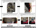
Conical Washer
Teeth side
against hitch
Always wear SAFETY GLASSES
when installing hitch.
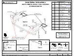
①
②
Frame Rail
Bulk Head
and Bumper
③
④
Access Hole
Figure 1
q
Drilled Hole
r
p
NOTE:
Nuts shown for clarity.
Nuts are inside of bumper beam.
Authorized Drawbar Kit:
3593
(Sold Separately)
Drawbar must be used in the
RISE
position only.